
Arduino library for Hobby Components mLink range of modules. This library currently supports the following mLink products:
mLink 12 Bit port expander (SKU: HCMODU0180)
mLink DHT22 temperature and humidity sensor (SKU: HCMODU0181)
mLink 1 channel relay module (SKU: HCMODU0182)
mLink 2 channel relay module (SKU: HCMODU0183)
mLink 4 channel relay module (SKU: HCMODU0184)
mLink RGBW light controller (SKU: HCMODU0185)
mLink NTC temperature sensor (SKU: HCMODU0186)
mLink Matrix 4x4 keypad (SKU: HCMODU0188)
mLink 1602 & 2004 Character LCD (SKU: HCMODU0190A & HCMODU0190B)
mLink 12864 Graphics LCD (SKU: HCMODU0189)
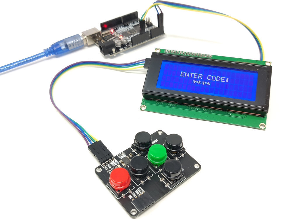
mLink 6 Button Keypad (SKU: HCMODU0193)
mLink Home Sensor (SKU: HCMODU0198)
mLink TMP36 Temperature Sensor Module (SKU: HCMODU0187)
mLink L9110 DC Motor Controller (SKU: HCMODU0199)
mLink WS2812 RGB LED controller (HCMODU0197)
mLink LongReach LoRa Transceiver (HCMODU0250)
Using the mLink library
Step 1) Downloading the mLink library
The library is available via several sources:
1) The latest version of the library can be downloaded from our forum here: https://hobbycomponents.com/downloads/m ... V2_3_0.zip
2) Via our github page here: https://github.com/HobbyComponents/mLink
3) For PlatformIO users you can add the library to your project by going to the library section of PlatformIO and searching either 'hobbycomponents' to view a list of our libraries or 'mLink' to just list the mLink library.
Step 2) Installing the mLink Library to the Arduino IDE
Once downloaded, open up your Arduino IDE and go to Sketch->Include Library->Add .ZIP Library.
In the file selection dialogue window that opens up, navigate to wherever you downloaded the mLink .zip file and select it, then click the ‘Open’ button.
Alternatively you can just unzip the library into your Arduino library folder usually found in the following location:
On Windows:
My Documents\Arduino\libraries\
On Mac:
Documents/Arduino/libraries/
Linux:
Usually found within the users home area under /Arduino/libraries/
Step 3) Including the mLink library in your sketch
Adding the mLink library to your sketch consists of 3 steps; Firstly, include the mLink header file (mLink.h) at the top of your sketch, create an instance of the library, then finally initialise the library inside the startup() function:
- // Step 1: Include the mLink library
- #include "mLink.h"
- //Step 2: Create an instance of the library
- mLink mLink;
- void setup()
- {
- // Step 3: Initialise the library
- mLink.init();
- }
- void loop()
- {
- }
The mLink library can be used to control any type of mLink module. For specific instructions and example sketches for your mLink module please see the documentation in the products forum thread (https://hobbycomponents.com/mLink), or the example sketches found within the mLink library.
Library Functions
mLink DHT22
mlink.DHT22_Start(add)			// Triggers a new temp/hum measurement.
busy = mlink.DHT22_Busy			// Measurement in progress
temp= mlink.DHT22_Temp(add)		// Returns the temperature as a float in oC to 1dp
hum = mlink.DHT22_Hum(add)		// Returns the humidity as a float in RH% to 1dp
Where:
add = The I2C address of the module
busy = Returns true if there is a measurement in progress, false if measurement is complete
temp = A float containing the last temperature measurement in oC to 1dp.
hum = A float containing the last humidity measurement in %RH to 1dp.
mLink 1Ch, 2CH, & 4CH relays
mlink.SET_RLY0(add, state)		// Sets the state of relay 0
mlink.SET_RLY1(add, state)		// Sets the state of relay 1
mlink.SET_RLY2(add, state)		// Sets the state of relay 2
mlink.SET_RLY3(add, state)		// Sets the state of relay 3

state = mlink.READ_RLY0(add)		// Returns the state of relay 0
state = mlink.READ_RLY1(add)		// Returns the state of relay 1
state = mlink.READ_RLY2(add)		// Returns the state of relay 2
state = mlink.READ_RLY3(add)		// Returns the state of relay 3

mlink.RLY0_SetOnTime(add, time)	// Sets relay 0 on time in seconds
mlink.RLY1_SetOnTime(add, time)	// Sets relay 1 on time in seconds
mlink.RLY2_SetOnTime(add, time)	// Sets relay 2 on time in seconds
mlink.RLY3_SetOnTime(add, time)	// Sets relay 3 on time in seconds

Firmware version 1.01 onwards:
mLink.RLY_ON(add, index)			// Turns the specified relay ON (restarts the timer if enabled).
mLink.RLY_OFF(add, index)		// Turns the specified relay OFF (cancels the timer if enabled).
mLink.RLY0_TIMER_RES(add, res)	// Sets the timer resolution for Relay 0.
mLink.RLY1_TIMER_RES(add, res)	// Sets the timer resolution for Relay 1.
mLink.RLY2_TIMER_RES(add, res)	// Sets the timer resolution for Relay 2.
mLink.RLY3_TIMER_RES(add, res)	// Sets the timer resolution for Relay 3.
Where:
add = The I2C address of the module
state = A boolean value (True / False) where True = Relay on, False = Relay off
time = A 16 bit integer containing the relay on time. 0 = timer disabled, 65535 = max
index = Relay index (0 to 3).
res = Timer resolution (0 = 1 second (default), 1 = 100ms).
mLink NTC temperature sensor
temp = mlink.NTC_Temp(add) // Returns the temperature as a float in oC to 1dp
Where:
add = The I2C address of the module
temp = A float containing the last temperature measurement in oC to 1dp.
mLink 4x4 matrix keypad
key = mLink.read(add, KEYPAD_4X4_KEY)						// Returns the next key press from the buffer
state = mLink.Keypad_4x4_Key_Down(add)					// Returns True if a key is currently pressed, False if no key is pressed
mLink.write (KEYPAD_4X4_I2C_ADD , KEYPAD_4X4_DEBOUNCE , db);	// Sets the amount of key debouncing
Where:
add = The I2C address of the module
key = ASCII value of the last key pressed or 255 if no key has been pressed
state = A boolean value containing the key state. 0 = not pressed & 1 = currently pressed
db = The amount of debouncing required (max = 254)
mLink 1602 & 2004 Character LCD
mLink.cLCD_cursor(add, col, row)	// Sets the cursors column and row position
mLink.cLCD_clear(add)			// Clears the display
mLink.cLCD_on(add, state)		// Turns the display on or off
mLink.cLCD_cursDir(add, dir)		// Sets the direction the cursor will move after printing a character - see note
mLink.cLCD_dispType(add, type) 	// Sets the display size - see note
mLink.cLCD_backlight(add, level)	// Sets the backlight brightness level
mLink.cLCD_contrast(add, level)	// Sets the contrast level
mLink.cLCD_print(add, text)		// Prints a string of text starting at the current cursor position
mLink.cLCD_printFloat(add, val, dp) 	// Prints a floating point number
mLink.cLCD_printCust(add, index)	// Writes one of the 8 custom characters to the display
mLink.cLCD_setCust0(add, bitmap)	// Writes a custom bitmap to custom character 0
mLink.cLCD_setCust1(add, bitmap)	// Writes a custom bitmap to custom character 1
mLink.cLCD_setCust2(add, bitmap)	// Writes a custom bitmap to custom character 2
mLink.cLCD_setCust3(add, bitmap)	// Writes a custom bitmap to custom character 3
mLink.cLCD_setCust4(add, bitmap)	// Writes a custom bitmap to custom character 4
mLink.cLCD_setCust5(add, bitmap)	// Writes a custom bitmap to custom character 5
mLink.cLCD_setCust6(add, bitmap)	// Writes a custom bitmap to custom character 6
mLink.cLCD_setCust7(add, bitmap)	// Writes a custom bitmap to custom character 7
Where:
add = The I2C address of the module
col = Cursor column position where 0 = left most column and 15 (1602) or 19 (2004) is right most column
row = Cursor row position where 0 = top row, 1 (1602) or 3 (2004) is the bottom row
text = A string of text to print to the screen
val = A floating point number
dp = the number of decimal places to print val to
state = Display on / off state where 0 = off and 1 = on
dir = Cursor direction where direction = 0 is left to right and direction = 1 is right
type = Display type where 0 = 16x2 line display and 1 = 20x4 line display
level = Backlight level where 0 = off and 10 = max
Contrast = Contrast level where 0 = min, 255 = max
index = The index (0 to 7) of the custom character to print
bitmap = An array of 8 bytes containing the custom character bitmap to upload. See documentation for how to define a bitmap
Notes:
cLCD_cursDir & cLCD_dispType settings are stored in non-volatile memory and will retain their state after a power cycle.
16x2 & 20x4 displays are shipped with the correct display type already set and therefore there is no need to execute the cLCD_dispType command.
mLink TMP36 Temperature Sensor
temp = mLink.TMP36_Temp(add) // Returns the current temperature
Where
add = The I2C address of the module
temp = The current temperature in oC to 1 decimal place
mLink 6 button pad
mLink.bPad_Empty(add)				// Returns the state of the buffer where True = buffer empty, False = buffer contains one or more keys
mLink.bPad_Read(add)				// Returns the next key from the buffer
mLink.bPad_UpState(add)				// Returns True if the Up key is currently pressed, False if not
mLink.bPad_LeftState(add)			// Returns True if the Left key is currently pressed, False if not
mLink.bPad_DownState(add)			// Returns True if the Down key is currently pressed, False if not
mLink.bPad_RightState(add)			// Returns True if the Right key is currently pressed, False if not
mLink.bPad_SelectState(add)			// Returns True if the Select key is currently pressed, False if not
mLink.bPad_BackState(add)			// Returns True if the Back key is currently pressed, False if not
mLink.bPad_Debounce(add, debounce)	// Sets the amount of debouncing
Where:
add = The I2C address of the module
debounce = The level of debouncing to apply to each keypress where 0 is none, 254 is max
mLink home sensor
mLink.HSense_Start_Meas(add)		// Triggers the start of a new temperature/humidity, use ml.busy(add) to test when measurement is complete
mLink.HSens_Temp(add)			// Returns the temperature in oC as a floating point value to 1dp
mLink.HSens_Hum(add)			// Returns the humidity in RH% as a floating point value to 1dp
mLink.HSens_DHT22_Error(add)		// Returns true if the current measurement was read from the DHT22 was valid, false if there was an error
mLink.HSens_LDR(add)			// Returns a light level sensed by the LDR sensor where 0 = dark and 255 = maximum brightness
mLink.HSens_PIR(add)			// Returns a light level sensed by the LDR sensor where 0 = dark and 255 = maximum brightness
mLink.HSens_Trigs(add)			// Returns a 16 bit integer containing the amount of times the PIR sensor has been triggered since last reset
mLink.HSens_Clear_Trigs(add)		// Resets the PIR trigger counter
mLink.HSense_Start_Meas(add)		// Triggers the start of a new temperature/humidity, use mLink.busy(add) to test when measurement is complete
Where:
add = The I2C address of the module
mLink NEC IR Transceiver
mLink.IR_Write_Data(add, data)			// Writes a 4 byte list to the Tx buffer
mLink.IR_Write_NEC(add, iradd, irdat)		// Writes an NEC address and command to the Tx buffer for transmitting
rxcount =  mLink.IR_Count(add)				// Returns the amount of times an IR message (inc repeat codes) has been received
valid = mLink.IR_NEC_Valid(add)			// Returns true if the last message received was a valid NEC message
mLink.IR_Read(add, data)					// Returns the last message received as a 4 byte list
iradd =mLink.IR_Read_NEC_Add(add)			// Returns the NEC address byte from a received IR message
irdat = mLink.IR_Read_NEC_Command(add)	// Returns the NEC command byte from a received IR message
mLink.IR_Send(add, count)				// Triggers a transmit of the message stored in the Tx buffer
mLink.IR_Com_LED_Mode(add, mode)		// Sets the mode of the COM LED
Where:
add = The I2C address of the module
iradd = NEC IR address byte
irdat = NEC IR command byte
count = Amount of times to transmit the message including repeat codes. Valid values are:
	If count = 1 then the message will be transmitted once
	If count = 1 + n then the message will be transmitted once + n x repeat codes
	If count = 255 then a single repeat code will be sent
data = a list of 4 bytes containing the IR message
mode = The required LED mode. Valid values are:
	IR_COM_LED_I2C = LED will illuminate during I2C bus transfers
	IR_COM_LED_IR = LED will illuminate whilst IR data is being received or transmitted
rxcount = The amount of times, including repeat codes, the IR message was received
valid = last received code was a valid NEC message
mLink L9110 DC Motor Controller
mLink.L9110_M1_Speed(add, speed)		// Sets the speed of motor M1
mLink.L9110_M2_Speed(add, speed)		// Sets the speed of motor M2
mLink.L9110_M1_Dir(add, dir)			// Sets the direction of motor M1
mLink.L9110_M2_Dir(add, dir)			// Sets the direction of motor M2
mLink.L9110_M1_Stop(add)			// Stops motor M1
mLink.L9110_M2_Stop(add)			// Stops motor M2
Where:
add = The I2C address of the module
speed = A value between 0 and 255 that sets the speed of the motor
direction = Sets the direction of rotation. Valid values are:
	REVERSE
	FORWARD
mLink WS2812 RGB LED Controller
mLink.WS2812_Max(add, maxIndex)			// Sets the number of LEDs connected
mLink.WS2812_Index(add, ledIndex)			// Sets the index of the LED to modify
mLink.WS2812_Red(add, redLevel)			// Sets the red level of the selected LED
mLink.WS2812_Green(add, greenLevel)		// Sets the green level of the connected LED
mLink.WS2812_Blue(add, blueLevel)			// Sets the blue level of the connected LED
mLink.WS2812_Refresh(add)				// Writes the buffer to the LEDs
mLink.WS2812_Clear(add)					// Sets the RGB levels off all leds to 0 (off)
mLink.WS2812_Brightness(add, bri)			// Sets the maximum brightness of the LEDs
mLink.WS2812_On(add, state)				// Turns all LEDs on or off
mLink.WS2812_Order(add, order)			// Sets the RGB order of the LEDs
mLink.WS2812_RGB(add, index, redLevel, greenLevel, blueLevel)	// Sets the RGB levels of an LED
redLevel = mLink.WS2812_Get_Red(add)		// Gets the current red level of the selected LED
greenLevel = mLink.WS2812_Get_Green(add)	// Gets the current green level of the selected LED
blueLevel = mLink.WS2812_Get_Blue(add)		// Gets the blue level of the selected LED
bri = mLink.WS2812_Get_Brightness(add)		// Gets the current brightness
state = mLink.WS2812_Get_On_State(add)		// Gets the on/off state of the LEDs
Where:
add = The I2C address of the module
maxIndex = The number of LEDs in your strip/module
ledIndex = The index of the LED to adjust
redLevel = The red level (0 to 255) of the LED at index ledIndex
greenLevel = The green level (0 to 255) of the LED at index ledIndex
blueLevel = The blue level (0 to 255) of the LED at index ledIndex
bri = The maximum brightness level (0 to 255) of the LED at index ledIndex
state = The on/off state of the LEDs. Valid values are
	0 = LEDs off
	1 = LEDs on
order = The RGB order of your LED strip. Valid values are:
	WS2812_ORDER_RGB (0)
	WS2812_ORDER_GRB (1)
mLink LongReach RM95 LoRa Transceiver
avail = mLink.LORA_Rx_Available(add)	// Checks to see if there is new Rx data available
size = mLink.LORA_Rx_Size(add)		// Gets the size of the received data
mLink.LORA_Rx_Read(add, size, rxarray)	// Reads the received data out of the Rx buffer
mLink.LORA_Rx_Address(add)			// Gets the address of the last received LongReach packet
mLink.LORA_Tx_Load(add, size, txarray)	// Loads data into the Tx buffer
mLink.LORA_Tx_Send(add)			// Sends the data in the Tx buffer
mLink.LORA_Tx_LR_Send(add, lrAdd)		// Sends the data in the Tx buffer as a LongReach packet
done = mLink.LORA_Tx_Done(add)		// Checks to see if the module has finished transmitting
mLink.LORA_Freq(add, freq)			// Sets the Tx/Rx frequency
mLink.LORA_Set_BW(add, bw)			// Sets the bandwidth
mLink.LORA_Set_SF(add, sf)			// Sets the spreading factor
rssi = mLink.LORA_RSSI(add)			// Returns the RSSI of the last received data
mLink.LORA_LR_Mode(add, lrmode)		// Enables/disables LongReach mode
mLink.LORA_Mode(add, mode)			// Changed the current radio mode
mLink.LORA_Resends(add, resends)		// Sets the amount of retransmits
mLink.LORA_Resend_Delay(add, delay)	// Sets the delay time between each resend
Where:
add = The I2C address of the module
size = The size in bytes of the data
rxarray = A byte array big enough to hold the received data
txarray = A byte array containing the data to be loaded into the Tx buffer
lrAdd = In LongReach mode this is the destination address the data will be sent to. In normal mode this is unused and can be any value.
freq = A unsigned in value containing the frequency in MHz
Bw = A byte value containing the bandwidth. Valid values are:
	LORA_BW_7_8KHz	(0)
	LORA_BW_10_4KHz	(1)
	LORA_BW_15_6KHz	(2)
	LORA_BW_20_8KHz	(3)
	LORA_BW_31_25KHz	(4)
	LORA_BW_41_7KHz	(5)
	LORA_BW_62_5KHz	(6)
	LORA_BW_125KHz	(7)
	LORA_BW_250KHz	(8)
	LORA_BW_500KHz	(9)
sf = A byte value containing the spreading factor. Valid values are:
	LORA_SF_64	(6)
	LORA_SF_128	(7)
	LORA_SF_256	(8)
	LORA_SF_512	(9)
	LORA_SF_1024	(10)
	LORA_SF_2048	(11)
	LORA_SF_4096	(12)
lrmode = The LongReach mode where 0 = disabled (normal), 1 = enabled (LongReach mode)
mode = A byte value representing the required radio mode. Valid value for mode are:
	LORA_MODE_SLEEP
	LORA_MODE_STDBY
	LORA_MODE_TRANSMIT
	LORA_MODE_RXCONTINUOUS
	LORA_MODE_RXSINGLE
resends = A byte value containing the number of resend (max = 10)
delay = An unsigned int containing the resend delay time in milliseconds (min = 100, max = 65535)
mLink 12 Channel Servo Controller
mLink.servo_On(add, servo)			// Turns the output of the indexed servo ON
mLink.servo_Off(add, servo)			// Turns the output of the indexed servo OFF
mLink.servo0_On(add)				// Turns the output of servo 0 ON
mLink.servo1_On(add) 				// Turns the output of servo 1 ON
mLink.servo2_On(add)				// Turns the output of servo 2 ON
mLink.servo3_On(add)				// Turns the output of servo 3 ON
mLink.servo4_On(add) 				// Turns the output of servo 4 ON
mLink.servo5_On(add)				// Turns the output of servo 5 ON
mLink.servo6_On(add)				// Turns the output of servo 6 ON
mLink.servo7_On(add)				// Turns the output of servo 7 ON
mLink.servo8_On(add)				// Turns the output of servo 8 ON
mLink.servo9_On(add)				// Turns the output of servo 9 ON
mLink.servo10_On(add)				// Turns the output of servo 10 ON
mLink.servo11_On(add)				// Turns the output of servo 11 ON
mLink.servo0_Off(add)				// Turns the output of servo 0 OFF
mLink.servo1_Off(add)				// Turns the output of servo 1 OFF
mLink.servo2_Off(add)				// Turns the output of servo 2 OFF
mLink.servo3_Off(add)				// Turns the output of servo 3 OFF
mLink.servo4_Off(add)				// Turns the output of servo 4 OFF
mLink.servo5_Off(add)				// Turns the output of servo 5 OFF
mLink.servo6_Off(add)				// Turns the output of servo 6 OFF
mLink.servo7_Off(add)				// Turns the output of servo 7 OFF
mLink.servo8_Off(add)				// Turns the output of servo 8 OFF
mLink.servo9_Off(add)				// Turns the output of servo 9 OFF
mLink.servo10_Off(add)				// Turns the output of servo 10 OFF
mLink.servo11_Off(add)				// Turns the output of servo 11 OFF
mLink.servo0_Pos(add, pos)			// Sets the position of servo 0
mLink.servo1_Pos(add, pos)			// Sets the position of servo 1
mLink.servo2_Pos(add, pos)			// Sets the position of servo 2
mLink.servo3_Pos(add, pos)			// Sets the position of servo 3
mLink.servo4_Pos(add, pos)			// Sets the position of servo 4
mLink.servo5_Pos(add, pos)			// Sets the position of servo 5
mLink.servo6_Pos(add, pos)			// Sets the position of servo 6
mLink.servo7_Pos(add, pos)			// Sets the position of servo 7
mLink.servo8_Pos(add, pos)			// Sets the position of servo 8
mLink.servo9_Pos(add, pos)			// Sets the position of servo 9
mLink.servo10_Pos(add, pos)			// Sets the position of servo 10
mLink.servo11_Pos(add, pos)			// Sets the position of servo 11
mLink.servo0_LimLow(add, pos)		// Sets the lower limit for servo 0
mLink.servo1_LimLow(add, pos)		// Sets the lower limit for servo 1
mLink.servo2_LimLow(add, pos)		// Sets the lower limit for servo 2
mLink.servo3_LimLow(add, pos)		// Sets the lower limit for servo 3
mLink.servo4_LimLow(add, pos)		// Sets the lower limit for servo 4
mLink.servo5_LimLow(add, pos)		// Sets the lower limit for servo 5
mLink.servo6_LimLow(add, pos)		// Sets the lower limit for servo 6
mLink.servo7_LimLow(add, pos)		// Sets the lower limit for servo 7
mLink.servo8_LimLow(add, pos)		// Sets the lower limit for servo 8
mLink.servo9_LimLow(add, pos)		// Sets the lower limit for servo 9
mLink.servo10_LimLow(add, pos)		// Sets the lower limit for servo 10
mLink.servo11_LimLow(add, pos)		// Sets the lower limit for servo 11
mLink.servo0_LimHigh(add, pos)		// Sets the upper limit for servo 0
mLink.servo1_LimHigh(add, pos)		// Sets the upper limit for servo 1
mLink.servo2_LimHigh(add, pos)		// Sets the upper limit for servo 2
mLink.servo3_LimHigh(add, pos)		// Sets the upper limit for servo 3
mLink.servo4_LimHigh(add, pos)		// Sets the upper limit for servo 4
mLink.servo5_LimHigh(add, pos)		// Sets the upper limit for servo 5
mLink.servo6_LimHigh(add, pos)		// Sets the upper limit for servo 6
mLink.servo7_LimHigh(add, pos)		// Sets the upper limit for servo 7
mLink.servo8_LimHigh(add, pos)		// Sets the upper limit for servo 8
mLink.servo9_LimHigh(add, pos)		// Sets the upper limit for servo 9
mLink.servo10_LimHigh(add, pos)		// Sets the upper limit for servo 10
mLink.servo11_LimHigh(add, pos)		// Sets the upper limit for servo 11
mLink.servo_Save_State(add)			// Saves the current lower, upper, and servo position to NVM
mLink.servo_Save_Defaults(add)		// Resets NVM to default lower, upper, and servo position

Where:
add = The I2C address of the module
servo = The servo index (0 to 11)
pos = The servo position (0 to 255)
FAQ:
I get a library not found error when trying to compile a sketch.
Go to your libraries folder and check that the mLink library folder is named 'mLink' and not 'mLink_Vx_x_x'. If you still get the error after renaming the folder then try restarting the Arduino IDE.
Diagrams, libraries, and example code are provided as an additional free service by Hobby Components and are not sold as part of this product. We do no provide any guarantees or warranties as to their accuracy or fitness for purpose.
Descriptions and diagrams on this page are copyright Hobby Components Ltd and may not be reproduced without permission.