mLink 12Ch Servo Controller (HCMODU0263)

mLink serial I2C modules
Post Reply
admin
Site Admin
Posts: 881
Joined: Sun Aug 05, 2012 4:02 pm

mLink 12Ch Servo Controller (HCMODU0263)

Post by admin » Wed Dec 18, 2024 3:49 pm

Image


Image

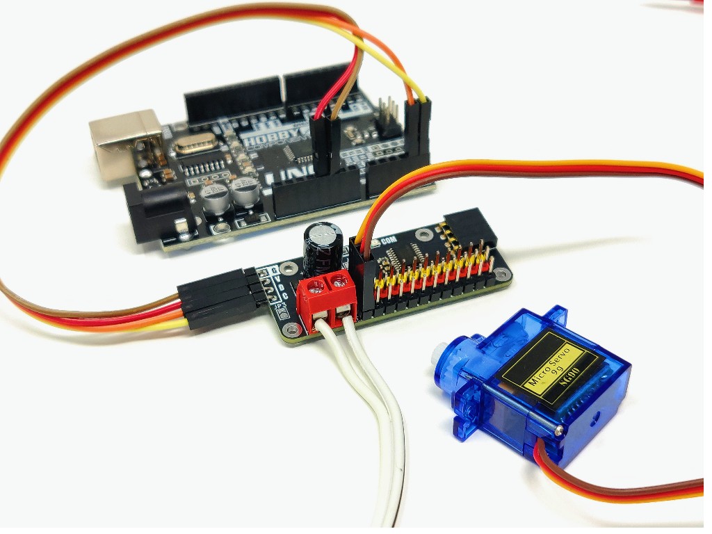
The mLink 12-Channel Servo Controller allows you to independently control up to 12 servos per module via a microcontroller's serial I²C interface. It supports standard PWM-controlled servos from popular brands like Tower Pro, Futaba, JR, Hitec, Emax, and more.


Image


Servo Connection Features
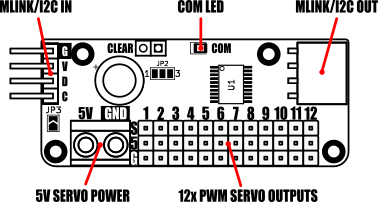
  - 12 Headers: Each servo connects to a dedicated 3-pin header (0.1” pitch) providing:
  - GND
  - 5V power
  - PWM signal
External Power Support: External 5V power for servos can be supplied via a screw terminal for increased current handling.


PWM Control Capabilities
  - Independent Channels: Generates 12 unique PWM signals.
  - 20 ms Duty Cycle: Each signal is refreshed every 20 ms.
  - On-Time Range: PWM on-time adjustable between 10 µs and 2.55 ms, divided into 256 steps.
  - Servo Precision: For standard servos (requiring 1 to 2 ms on-time), this provides up to 100 steps of resolution per servo, ensuring smooth and accurate movement.


mLink I²C Interface
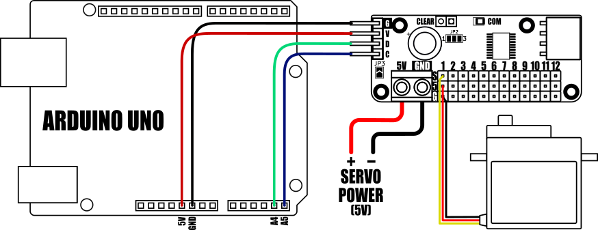
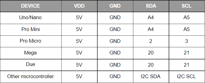
  - Microcontroller Compatibility: Works with any microcontroller or development board with an I²C interface.
  - Expandable System: Part of the mLink ecosystem, allowing seamless daisy-chaining with other mLink modules (e.g., LCD displays, keypads, sensors, relays) through a single I²C connection.
  - Simple Software Integration: Only one compact library is needed to control the entire mLink system.


Arduino & Raspberry Pi Support
  - Arduino: A dedicated mLink library simplifies servo control with intuitive functions.
  - Raspberry Pi: A Python module is available for easy integration.
  - Resources: Examples and library links are provided to help you get started quickly.


This controller offers a robust, scalable, and user-friendly solution for projects involving multiple servos.


Module Specifications
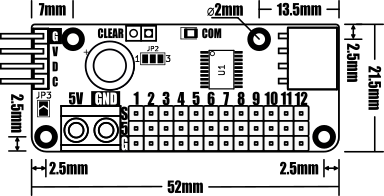
Module code:				HCMODU0263
Module supply voltage:		4.5V to 5.5V (via mLink header)
Supply current (module only):	4.6mA (normal) ~300uA (sleep)
Number of servo outputs:		12
Servo output type:			PWM
Servo duty cycle:			20ms
Servo PWM on time (min):		10µs
Servo PWM on time (max):		2.55ms
Servo step resolution:		10µs
Servo interface:			12x 3-pin 0.1” pitch pin header (PWM, 5V, GND)
Servo supply input:			5V @ 5A max via screw terminal
I²C Interface speed:			400kbits/s (fast mode)
I²C default address (HEX):		0x60
Maximum number of modules:	5 with pullups fitted, 112 with pullups removed*
Module dimensions:			52mm x 21.5mm x 11.5mm (excluding headers)


*Note the maximum number of connected modules will depend on cable lengths and power requirements of each module. Do not exceed 5 mLink modules connected in series with I2C pullups fitted to all modules. For disconnecting pullups see forum post.


Image

Image


Image

Sweep Example

Sweep a servo back and forth:

This sketch demonstrates how to control a servo's position.
It steps the first servo through its default range of 100 to 200.

To extend the default range, refer to the range example sketch..

  1. #include "mLink.h"                            // Include the library
  2.  
  3. mLink mLink;                                  // Create an instance of the library
  4.  
  5. #define I2C_ADD 0x60                          // Default I2C address
  6.  
  7.  
  8. void setup()
  9. {
  10.   mLink.init();                               // Initialise the library
  11.  
  12.   mLink.servo0_On(I2C_ADD);                   // Enable output for the first servo
  13. }
  14.  
  15.  
  16. void loop()
  17. {
  18.   for(uint8_t i = 100; i <= 200; i++)         // Step forward though positions 100 to 200
  19.   {
  20.     mLink.servo0_Pos(I2C_ADD, i);  
  21.     delay(10);
  22.   }
  23.  
  24.   for(uint8_t i = 200; i >= 100; i--)         // Step backward though positions 200 to 100
  25.   {
  26.     mLink.servo0_Pos(I2C_ADD, i);  
  27.     delay(10);
  28.   }
  29. }

Set limits example

Set the upper and lower limits of a servo:

This sketch shows how to adjust the default upper and lower limits of a servo.
If your servo supports a wider range than the default (100 to 200), you can
increase the limits using this example.

To retain the servo limits after power is removed, use the
mLink.servo_Save_State() command to save the current settings. Alternatively, use
mLink.servo_Save_Defaults() to restore the default settings.

WARNING: Driving a servo beyond its maximum range can cause permanent damage.
Use this sketch carefully!

  1. #define LOWER_LIMIT 80
  2. #define UPPER_LIMIT 220
  3.  
  4. #include "mLink.h"                                    // Include the library
  5.  
  6. mLink mLink;                                          // Create an instance of the library
  7.  
  8. #define I2C_ADD 0x60                                  // Default I2C address
  9.  
  10.  
  11. void setup()
  12. {
  13.   mLink.init();                                       // Initialise the library
  14.  
  15.   mLink.servo0_LimLow(I2C_ADD, LOWER_LIMIT);          // Set lower limit for servo 0
  16.   mLink.servo0_LimHigh(I2C_ADD, UPPER_LIMIT);         // Set upper limit for servo 0
  17.  
  18.   //mLink.servo_Save_State(I2C_ADD);                  // Uncomment to save the new limits to NVM
  19.  
  20.   mLink.servo0_On(I2C_ADD);                           // Enable output for the first servo
  21. }
  22.  
  23.  
  24. void loop()
  25. {
  26.   for(uint8_t i = LOWER_LIMIT; i <= UPPER_LIMIT; i++) // Step forward though the new range
  27.   {
  28.     mLink.servo0_Pos(I2C_ADD, i);  
  29.     delay(10);
  30.   }
  31.  
  32.   for(uint8_t i = UPPER_LIMIT; i >= LOWER_LIMIT; i--) // Step backward though the new range
  33.   {
  34.     mLink.servo0_Pos(I2C_ADD, i);  
  35.     delay(10);
  36.   }
  37. }


Image

Image


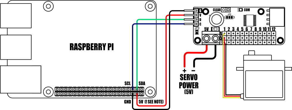
When connecting to a Raspberry Pi the mLink modules I2C pullup resistors should be removed. See the 'Removing the modules I2C pullup resistors' section below for more information.


Servo position example

Sweeps a servo back and forth:

mLink 12 channel servo sweep example
This example demonstrates how to set the position of a servo.

The example will sweep servo 0 back and forth between positions 100 to
200

  1. from mLink import mLink                         # Import the mLink module
  2. import time
  3.  
  4. ml = mLink.mLink(1)                             # Create an instance of the module
  5.  
  6. I2C_ADD = 0x60                                  # Default I2C address is 0x60
  7.  
  8.  
  9. ml.servo0_On(I2C_ADD)                           # Turn servo 0 ON
  10.  
  11.  
  12. while 1:
  13.     for i in range(100, 200):                   # Step forward through positions 100 to 200
  14.         ml.servo0_Pos(I2C_ADD, i)
  15.         time.sleep(0.01)
  16.    
  17.     for i in range(200, 100, -1):               # Step backwards through positions 200 to 100
  18.         ml.servo0_Pos(I2C_ADD, i)
  19.         time.sleep(0.01)

Set limits example

Set the limits of a servo:
This example demonstrates how to adjust the default upper and lower
limits of a servo.

If your servo supports a wider range than the default 100 to 200,
you can increase the limits using this example.

To retain the servo limits after power is removed, use the
ml.servo_Save_State() command to save the current settings.
Alternatively, use ml.servo_Save_Defaults() to restore the default
settings.

WARNING: Driving a servo beyond its maximum range can cause permanent
damage. Use this script carefully!

  1. LOWER_LIMIT = 80
  2. UPPER_LIMIT = 220
  3.  
  4.  
  5. from mLink import mLink                             # Import the mLink module
  6. import time
  7.  
  8. ml = mLink.mLink(1)                                 # Create an instance of the module
  9.  
  10. I2C_ADD = 0x60                                      # Default I2C address is 0x60
  11.  
  12.  
  13. ml.servo0_LimLow(I2C_ADD, LOWER_LIMIT)              # Set the low limit for servo 0
  14. ml.servo0_LimHigh(I2C_ADD, UPPER_LIMIT)             # Set the high limit for servo 0
  15. #ml.servo_Save_State(I2C_ADD)                       # Uncomment to save the new limits
  16.  
  17.  
  18. ml.servo0_On(I2C_ADD)                               # Turn servo 0 ON
  19.  
  20.  
  21. while 1:
  22.     for i in range(LOWER_LIMIT, UPPER_LIMIT):       # Step forward through 100 to 200
  23.         ml.servo0_Pos(I2C_ADD, i)
  24.         time.sleep(0.01)
  25.    
  26.     for i in range(UPPER_LIMIT, LOWER_LIMIT, -1):   # Step backwards through 200 to 100
  27.         ml.servo0_Pos(I2C_ADD, i)
  28.         time.sleep(0.01)


Image

Dimensions:

Image


Factory Reset:
Should you wish to restore the module back to its factory default configuration, this can be done by manually forcing a factory reset. All mLink modules include a set of pads labelled clear:

Image

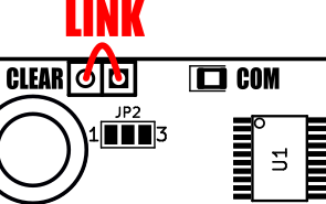
To perform a factory reset carefully link the two pads together with a piece of wire or with something conductive such as a paperclip. Whilst linked, connect power to the module via the VCC and GND connections. Wait a few seconds and then remove the short from the pads. The module's settings, including its I2C address, should now be restored back to factory defaults.


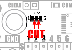
Removing I2C pullups:
If your development board already has pullups for its I2C interface fitted, or you wish to connect more than 5 mLink boards to the same I2C interface, then you can remove the pullups for the additional boards by cutting the tracks between the solder pads shown below.

Image


Image


mLink Arduino library

viewtopic.php?f=58&t=3001

Please note that you will need at least V2.2.0 (18 Dec 2024) of the library to support this module. If you have an older version already installed please update it to the latest version.


mLink Raspberry Pi Python module
The mLink python module can be installed with the following terminal command:

  1. pip install hc-mlink

Alternatively the library can be manually installed by downloading it from the forum and unzipping it to your project folder. See the Python module forum thread for more information and download link:
viewtopic.php?f=131&t=3062&p=8592#p8592

Please note that in some cases there may be additional configuration required. If you have issues getting your Raspberry Pi to communicate with the mLink module then please see the Python module forum thread here: viewtopic.php?f=131&t=3062


mLink Specifications and Register Map

https://hobbycomponents.com/downloads/m ... er_Map.pdf


Libraries, example code, and diagrams are provided as an additional free service by Hobby Components and are not sold as part of this product. We do not provide any guarantees or warranties as to their accuracy or fitness for purpose.

Post Reply

Return to “mLink”