
Description:
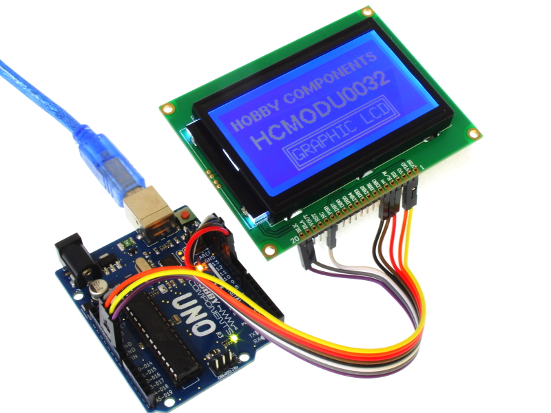
The 12864B Graphic LCD module is a 128 x 64 pixel LCD display with a blue backlight and white foreground. The display is fully programmable and can display a combination of both graphics and text. It can operate in both parallel and serial (SPI) modes which can be configured by the external pin PSB (please see note below). In SPI mode only 3 data pins are required to drive this display. No potentiometer is required to set the contrast as this is pre set by the factory to optimum level.
This item can be purchased here.
1)Encapsulation:COB(Chip-on-Board)
2)Display Format:128x64 dots
3)Display Type:STN, Transflective, Positive, Blue
4)Controller: ST7920
5)Interface:8-bit parallel interface or serial SPI modes
6)Backlight:Blue/Bottom light
7)Viewing Direction:6 O’clock
8)Driving Scheme:1/64 Duty Cycle, 1/9 Bias
9)Power Supply Voltage:5.0 V
10)VLCD Adjustable For Best Contrast:9.0 V (VOP.)
11)Operation temperature:-20°C to +70°C
12)Storage temperature :-30°C to +80°C
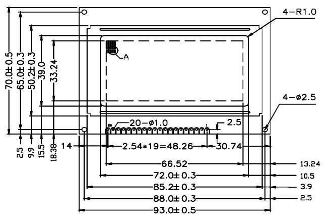
Dimensions:

NOTE:

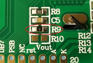
Some versions of this LCD are shipped with the PSB (parallel/serial select) pin shorted to VDD by a 0 ohm resistor fitted to R9 on the back of the LCD (see image above). This fixes the LCD in parallel mode. If this resistor is fitted and you wish to use the LCD in serial mode you will either need to move the resistor to R10 or completely remove it and ground the PSD pin.
Arduino Connections In Serial (SPI) Mode:
For Arduino Uno
MODULE..........................UNO
K (backlight cathode).........GND
A (backlight anode)..........+5V
PSD (SPI Mode).................GND (SEE NOTE)
E (SCK)..........................D13
R/W (MOSI)....................D11
RS (CS)..........................D10*
VDD.............................+5V
VSS..............................GND
For Arduino Mega
MODULE..........................MEGA
K (backlight cathode).........GND
A (backlight anode)..........+5V
PSD (SPI Mode).................GND (SEE NOTE)
E (SCK)..........................D52
R/W (MOSI)....................D51
RS (CS)..........................D53*
VDD.............................+5V
VSS..............................GND
*This pin is configured in software, see '#define CS_PIN 10' line in example sketch below.
Arduino Library:
This display is supported by our HCDisplay library. You can download the library from the software section of our support forum here:
viewtopic.php?f=58&t=2827
Arduino Example Sketch:
- /* FILE: HCDisplay_Hello_World
- DATE: 20/12/18
- VERSION: 0.1
- AUTHOR: Andrew Davies
- 20/12/18 version 0.1: Original version
- This is a simple sketch to demonstrates how to print text at specified locations
- on the display. The sketch also shows how to change font style and
- foreground/background colour. This sketch has been written to work with the
- following module:
- https://hobbycomponents.com/displays/285-12864b-parallel-serial-graphic-lcd-module
- The library support both hardware as software serial interfaces for this display.
- To use the hardware (SPI) interface connect the display to your UNO/NANO as follows:
- MODULE..........................UNO
- K (backlight cathode)...........GND
- A (backlight anode).............+5V
- PSD (SPI Mode)..................GND (SEE NOTE)
- E (SCK).........................D13
- R/W (MOSI)......................D11
- RS (CS).........................D10*
- VDD.............................+5V
- VSS.............................GND
- And initialise the library with the following function: HCDisplay.Init(10);
- For software serial you can use any digital pin for E (SLK), R/W (MOSI), & RS (CS).
- Initialise the library for software serial module with the following function:
- HCDisplay.Init(RS PIN, E PIN, R/W PIN);
- *Some versions of this LCD are shipped with the PSB (parallel/serial select) pin
- shorted to VDD by a 0 ohm resistor on the back of the display.
- NOTE: TO USE THIS SKETCH YOU MUST FIRST SELECT THE VERSION OF DISPLAY YOU HAVE BY
- UNCOMMENTING THE APPROPRIATE LINE IN THE OPTIONS.H FILE WHICH CAN BE FOUND IN THE
- HCDISPLAY LIBRARY FOLDER. For windows users avoid using the Windows Notepad editor
- as it doesn't format things properly.
- More information about this library can be found in the software section of our support
- forum here:
- http://forum.hobbycomponents.com/software
- You may copy, alter and reuse this code in any way you like, but please leave
- reference to HobbyComponents.com in your comments if you redistribute this code.
- This software may not be used directly for the purpose of selling products that
- directly compete with Hobby Components Ltd's own range of products.
- THIS SOFTWARE IS PROVIDED "AS IS". HOBBY COMPONENTS MAKES NO WARRANTIES, WHETHER
- EXPRESS, IMPLIED OR STATUTORY, INCLUDING, BUT NOT LIMITED TO, IMPLIED WARRANTIES OF
- MERCHANTABILITY AND FITNESS FOR A PARTICULAR PURPOSE, ACCURACY OR LACK OF NEGLIGENCE.
- HOBBY COMPONENTS SHALL NOT, IN ANY CIRCUMSTANCES, BE LIABLE FOR ANY DAMAGES,
- INCLUDING, BUT NOT LIMITED TO, SPECIAL, INCIDENTAL OR CONSEQUENTIAL DAMAGES FOR ANY
- REASON WHATSOEVER.
- */
- #include "HCDisplay.h"
- HCDisplay HCDisplay; //Creates an instance of the HCDisplay library
- /*******************************************************************************************************/
- /**************************************** USER SETTINGS ************************************************/
- /*******************************************************************************************************/
- /* Arduino pins used to connect to the display and displays touch sensor */
- #define RS 10 //Displays Chip Select pin
- #define E 13 //Displays clock pin
- #define RW 11 //Displays data pin
- /*******************************************************************************************************/
- unsigned int MaxX, MaxY;
- boolean FGColour = 1;
- void setup()
- {
- HCDisplay.Init(RS); //Initialise the display (hardware serial mode - faster but must use hardware SPI pins)
- //HCDisplay.Init(RS, E, RW); //Initialise the display (software serial mode - slower but can use any digital pins)
- /* Get the screens X & Y resolution */
- MaxX = HCDisplay.ResX() - 1;
- MaxY = HCDisplay.ResY() - 1;
- /* Draw a boarder */
- HCDisplay.Rect(0 , 0, MaxX, MaxY, OUTLINE, 1);
- HCDisplay.Rect(0 + 3 , 0 + 3, MaxX - 3, MaxY - 3, OUTLINE, 1);
- /* Print some text */
- HCDisplay.Pos(44,8);
- HCDisplay.Print("Hobby");
- HCDisplay.Pos(24,18);
- HCDisplay.Print("Components");
- HCDisplay.Pos(16,30);
- HCDisplay.Print("128 x 64 LCD");
- /* Change the font */
- HCDisplay.SetFont(MedProp_12ptFont);
- }
- void loop()
- {
- /* Make some text flash by swapping the text foreground and background colours */
- HCDisplay.SetFG(FGColour);
- HCDisplay.SetBG(!FGColour);
- HCDisplay.Pos(10,42);
- HCDisplay.Print("HCMODU0032");
- FGColour = !FGColour;
- delay(200);
- }
Datasheet: