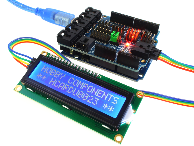

This 16 character by 2 line display has a very clear and high contrast white text upon a blue background/backlight. It also includes a serial I2C/IIC adaptor board pre-soldered to the back of the LCD. This means it can be controlled with just 2 I2C serial data pins (SDA & SCL) and so requires far less digital IO pins when controlled from a microcontroller. In total the module only requires 4 wires including 5V power and GND. Contrast adjustment is also provided by the daughter board via a potentiometer. If you plan to use this with an Arduino board you can download a compatible library and example sketch (see below).
posting.php?mode=edit&f=75&p=1132
Product Code HCARDU0023
Features 64mm x 14mm LCD display, supports IIC / I2C
Application DIY Arduino based project. Allows remote panel mounting. Requires only 2 IO pins.
- PINOUT
1.....GND
2.....VCC (+5V)
3.....SDA
4.....SCL
Notes:
These modules are currently supplied with a default I2C address of either 0x27 or 0x3F. To determine which version you have check the black I2C adaptor board on the underside of the module. If there a 3 sets of pads labelled A0, A1, & A2 then the default address will be 0x3F. If there are no pads the default address will be 0x27.
The module has a contrast adjustment pot on the underside of the display. This may require adjusting for the screen to display text correctly.
If pressure is applied to the I2C daughter board it is possible for it to bend and come contact with the LCD module. Please ensure when the LCD is installed in your application that no external object is applying pressure to the back of the module.

Arduino example
- * FILE: ARD_LCD_HCARDU0023_I2C_Hello_World_Example.pde
- DATE: 07/09/12
- VERSION: 0.1
- This is a simple example of how to use the Hobby Components I2C LCD module
- (HCARDU0023). To use this module you will require the appropriate library
- which can be downloaded from the modules section of our support forum at the
- following location:
- http://forum.hobbycomponents.com
- This code also demonstrates the correct pin assignment for the LCD. When you
- run this program you should see a greeting message appear on the display.
- DEVICE PINOUT (SPI Interface):
- PIN 1: GND
- PIN 2: +5V
- PIN 3: SDA - Connect to Arduino analogue PIN 4
- PIN 4: SCL - Connect to Arduino analogue PIN 5
- You may copy, alter and reuse this code in any way you like but please leave
- reference to hobbycomponents.com in your comments if you redistribute this code. */
- /* Include the SPI/IIC Library */
- #include <Wire.h>
- #include <LiquidCrystal_I2C.h>
- /* Initialise the LiquidCrystal library. Note that the displays will have a default I2C
- address of either 0x27 or 0x3F. Uncomment one of the lines below depending on
- the address of your module. */
- //LiquidCrystal_I2C lcd(0x27,16,2);
- //LiquidCrystal_I2C lcd(0x3F,16,2);
- void setup()
- {
- /* Initialise the LCD */
- lcd.begin();
- }
- /* Main program loop */
- void loop()
- {
- /* Make sure the backlight is turned on */
- lcd.backlight();
- /* Output the test message to the LCD */
- lcd.setCursor(0,0);
- lcd.print("HOBBY COMPONENTS");
- lcd.setCursor(0,1);
- lcd.print("**HELLO WORLD**");
- /* Do nothing */
- while(1);
- }

Libraries: EDIT (16/01/16): New version now works with Arduino IDE version 1.6.7
EDIT (01/12/12): New version 2.1 available. This should work with all versions of SDK
Datasheets:
FAQ:
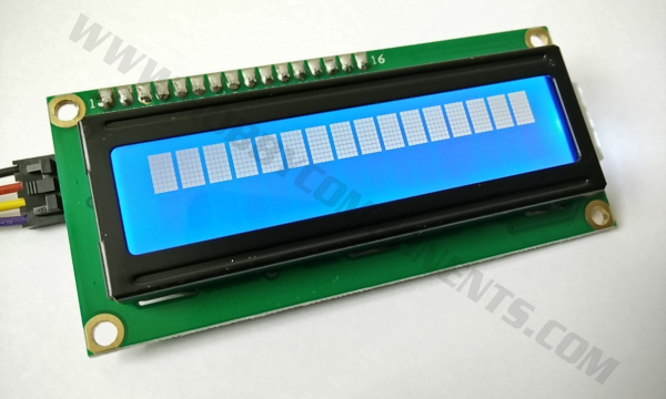
My screen just displays one row of squares along the top line. Is it faulty?

It is normal for the module when first powered up to display a row of solid squares as show above. If your display is still showing this after running your sketch then it is a sign that it is not initialising the module correctly for some reason. Normally this is caused by one of 3 things, a bad or incorrect connection to the I2C interface on the module, an incorrect I2C address (for our modules the default address is either 0x27 or 0x37), or by far the most common cause is using an incompatible version of the LiquidCrystal_I2C library. For our screens you should always use the version available for download in this post. If you have downloaded a version from elsewhere please also remember to delete it from your Arduino library folder(s) otherwise the Arduino IDE may still continue to use it.
The text of my screen is very faint
Under normal conditions text should be very clear and visible. If text on your module is hard to read this is normally caused by one of two things...
Firstly, this module requires the backlight to be on for text to be readable. If your backlight isn't on then check that there is a jumper fitted across the two pin header labelled 'LED' on the back of the module. This purpose of this jumper is to connect the 5V power to the backlight. Our modules are shipped with this jumper fitted but it is possible for it to shake loose during shipping. If the jumper is missing check the anti-static bag your module was shipped in.
If the backlight is on then see the next FAQ
My screen isn't displaying anything / my screen just displays two rows of solid squares
This could be caused by the screens contrast being set too low (no text) or too high (solid squares). On the back of the module there is a blue potentiometer, this adjusts the displays contrast. Normally our modules are shipped with it set to the ideal contrast position but in some cases it may need adjusting.
Libraries, example code, and diagrams are provided as an additional free service by Hobby Components and are not sold as part of this product. We do no provide any guarantees or warranties as to their accuracy or fitness for purpose.
Descriptions and diagrams on this page are copyright Hobby Components Ltd and may not be reproduced without permission.