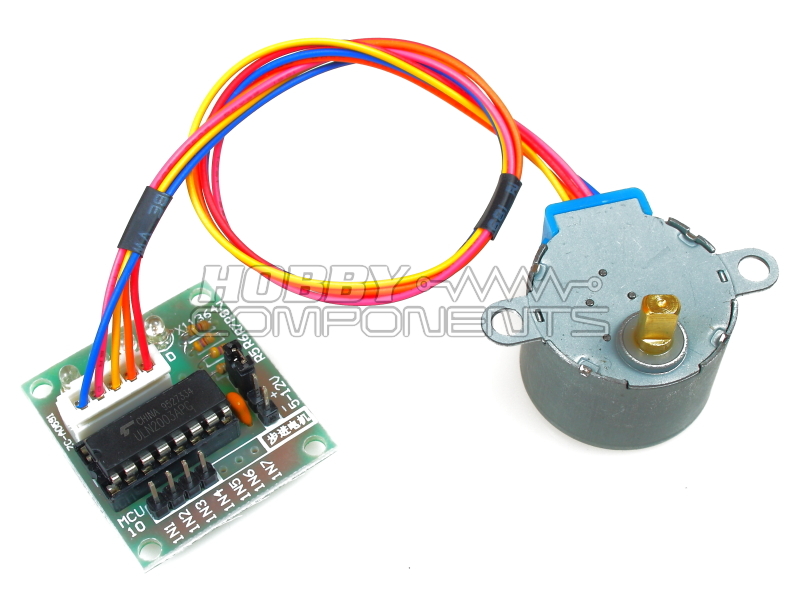

4 phase DC stepper motor with included driver interface board. Stepper motor has 1:64 ratio gear box. Can be driven in both forward and reverse directions. Works with standard Arduino stepper motor library.
Please note: The +/- power connector is marked with a 5-12V input. This is because the same driver board can be used with the 12V version of the stepper motor. You should not apply more than 5V to the supply input as you will damage the stepper motor.
Motor Features:
Diameter: 28mm
Voltage: 5V
Step angle: 5.625 x 1/64
Reduction ratio: 1/64
ULN2003 Driver Board:
A, B, C, D LED indication for four-phase stepper motor status
Size: 31x35mm
PINOUT:
MCU interface
IN1.....Input drive to motor coil A (HIGH/5V = Coil energised)
IN2.....Input drive to motor coil B (HIGH/5V = Coil energised)
IN3.....Input drive to motor coil C (HIGH/5V = Coil energised)
IN4.....Input drive to motor coil D (HIGH/5V = Coil energised)
IN5.....N/A
IN6.....N/A
IN7.....N/A
Power
1 (-)......0V/GND
2 (+).....5V
3...........Connect to 4 with jumper
4...........Connect to 3 with jumper
Motor
1..........Coil A
2..........Coil B
3..........Coil C
4..........Coil D
5..........5V power (via Power connector pin 4)

Code: Select all
/* FILE:    ARD_Stepper_Motor_HCARDU0035_Example.pde
   DATE:    02/09/12
   VERSION: 0.1

This is an example of how to use the HobbyComponents Arduino compatable stepper
motor with driver interface (HCARDU0035) . When run this program will
continually
rotate the motor one full revolution the the forward direction
followed by one full
revolution in the reverse direction. Although this stepper motow will
work with the
standard Arduino stepper motor library functions, this priogram
demonstates how easy
it is to directly control.

You may copy, alter and reuse this code in any way you like, but please leave
reference to HobbyComponents.com in your comments if you redistribute
this code.

THIS SOFTWARE IS PROVIDED "AS IS". HOBBY COMPONENTS MAKES NO
WARRANTIES, WHETHER
EXPRESS, IMPLIED OR STATUTORY, INCLUDING, BUT NOT LIMITED TO, IMPLIED
WARRANTIES OF
MERCHANTABILITY AND FITNESS FOR A PARTICULAR PURPOSE, ACCURACY OR LACK
OF NEGLIGENCE.
HOBBY COMPONENTS SHALL NOT, IN ANY CIRCUMSTANCES, BE LIABLE FOR ANY DAMAGES,
INCLUDING, BUT NOT LIMITED TO, SPECIAL, INCIDENTAL OR CONSEQUENTIAL
DAMAGES FOR ANY
REASON WHATSOEVER.

*/


/* Defines the vales passed to the function vStepMotor()
   to specify which direction you would like the motor to
   turn in. */

#define FORWARD true
#define REVERSE false

/* Defines the digital IO pins used to control each of
   the stepper motors coils. */

#define MOTOR_COIL_1_DIO 8
#define MOTOR_COIL_2_DIO 9
#define MOTOR_COIL_3_DIO 10
#define MOTOR_COIL_4_DIO 11

/* The number of steps for 1 revolution of this stepper
   motor is 360 degrees devided by the motor step angle
   of 5.625 multiplied by the gear ratio 1/64 multiplied
   by the number of coils 4 devided by two.
   Therefore: 360 / (5.625 * (1 / 64)) = 512 */

#define STEPSPER1REV 512


/* Set the 4 DIO pins used to drive the stepper motor to outputs */
void setup()
{
  pinMode(MOTOR_COIL_1_DIO, OUTPUT);
  pinMode(MOTOR_COIL_2_DIO, OUTPUT);
  pinMode(MOTOR_COIL_3_DIO, OUTPUT);
  pinMode(MOTOR_COIL_4_DIO, OUTPUT);
}

/* MAIN PROGRAM */
void loop()
{
  /* Used for counting the number of steps the motor has made */
  word u16StepCounter;

  /* Rotate the stepper motor one full forward revolution */
  for (u16StepCounter = 0; u16StepCounter < STEPSPER1REV; u16StepCounter++)
  {
    vStepMotor(FORWARD, 3);
  }

  /* Rotate the stepper motor one full reverse revolution */
  for (u16StepCounter = 0; u16StepCounter < STEPSPER1REV; u16StepCounter++)
  {
    vStepMotor(REVERSE, 3);
  }
}

/* Function will pulse all four coils of the sterrper motor in either
the forward
   or reverse directions. The function accepts to inputs, a true or a
false denoting
   the direction the motor should turn in (true = forward, false =
reverse), and a setp
   delay time in milliseconds between each step. */

void vStepMotor(boolean bDirection, word u16StepDelay)
{
  /* Holds which DIO pin is currently asciated with which motor coil */
  byte bMotorCoil_1;
  byte bMotorCoil_2;
  byte bMotorCoil_3;
  byte bMotorCoil_4;

  /* Set the order of the DIO pins depending on the direction the
     motor is requires to turn in. */
  if (bDirection == true)
  {
    bMotorCoil_1 = MOTOR_COIL_1_DIO;
    bMotorCoil_2 = MOTOR_COIL_2_DIO;
    bMotorCoil_3 = MOTOR_COIL_3_DIO;
    bMotorCoil_4 = MOTOR_COIL_4_DIO;
  }else
  {
    bMotorCoil_1 = MOTOR_COIL_4_DIO;
    bMotorCoil_2 = MOTOR_COIL_3_DIO;
    bMotorCoil_3 = MOTOR_COIL_2_DIO;
    bMotorCoil_4 = MOTOR_COIL_1_DIO;
  }


  /* Pulse each of the stepper motors coils in a sequencial order */
  digitalWrite(bMotorCoil_1, HIGH);
  digitalWrite(bMotorCoil_2, LOW);
  digitalWrite(bMotorCoil_3, LOW);
  digitalWrite(bMotorCoil_4, LOW);

  delay(u16StepDelay);

  digitalWrite(bMotorCoil_1, LOW);
  digitalWrite(bMotorCoil_2, HIGH);
  digitalWrite(bMotorCoil_3, LOW);
  digitalWrite(bMotorCoil_4, LOW);

  delay(u16StepDelay);

  digitalWrite(bMotorCoil_1, LOW);
  digitalWrite(bMotorCoil_2, LOW);
  digitalWrite(bMotorCoil_3, HIGH);
  digitalWrite(bMotorCoil_4, LOW);

  delay(u16StepDelay);

  digitalWrite(bMotorCoil_1, LOW);
  digitalWrite(bMotorCoil_2, LOW);
  digitalWrite(bMotorCoil_3, LOW);
  digitalWrite(bMotorCoil_4, HIGH);

  delay(u16StepDelay);

  digitalWrite(bMotorCoil_1, LOW);
  digitalWrite(bMotorCoil_2, LOW);
  digitalWrite(bMotorCoil_3, LOW);
  digitalWrite(bMotorCoil_4, LOW);
}