2.4" Colour TFT Module With Resistive Touch (HCMODU0133)

LCD, TFT, OLED, LED modules
Post Reply
admin
Site Admin
Posts: 884
Joined: Sun Aug 05, 2012 4:02 pm

2.4" Colour TFT Module With Resistive Touch (HCMODU0133)

Post by admin » Fri Feb 22, 2019 2:34 pm

Image


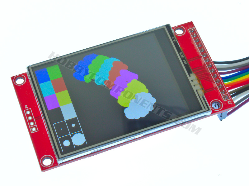
A 2.4" colour TFT display module compatible with 3.3V microcontrollers such as the Arduino Due, 3.3V Pro mini, 3.3V Pro micro, ESP8266, ESP32 etc. The module uses a standard serial SPI interface for communication. Besides featuring a 65K Colour display the module also includes a resistive touch sensor allowing your application to include touch input. Additionally the module features an SD card socket to add the option of storing image data on SD card.

ImageImage

If using this module with the Arduino board such as the *Uno, *Leonardo, *Pro Mini, *Pro Micro or Due we have also written an Arduino library (HCDisplay) which will allow you to develop your project with the minimum of effort.

*Note if using with 5V microcontrollers this module will require level shifters.


SPECIFICATION:

Product code: HCMODU0133
Display size: 2.4 inch
Resolution: 240X320
Display controller: ILI9341
Touch screen controller: TSC2046
Colours: 65535
Operating voltage: 5V
Touch screen type: resistive touchscreen
On board SD slot
Touch Pen: length 9cm


ARDUINO SKETCH:
  1. /* FILE:    HCDisplay_Hello_World
  2.    DATE:    22/02/19
  3.    VERSION: 0.1
  4.    AUTHOR:  Andrew Davies
  5.    
  6. 20/12/18 version 0.1: Original version
  7.  
  8. A simple hello world sketch to demonstrate the minimum amount of code needed to
  9. display some text to the screen.
  10.  
  11. 2.4 inch TFT LCD Module with Touch Panel ILI9341 240 x 320 (SKU: HCMODU0133)
  12.  
  13. NOTE: TO USE THIS SKETCH YOU MUST FIRST SELECT THE VERSION OF DISPLAY YOU HAVE BY
  14. UNCOMMENTING THE APPROPRIATE LINE IN THE OPTIONS.H FILE WHICH CAN BE FOUND IN THE
  15. HCDISPLAY LIBRARY FOLDER. For windows users, avoid using the Windows Notepad editor
  16. as it doesn't format things properly.  
  17.  
  18. More information about this library can be found in the software section of our support
  19. forum here:
  20.  
  21. http://forum.hobbycomponents.com/software
  22.  
  23.  
  24. You may copy, alter and reuse this code in any way you like, but please leave
  25. reference to HobbyComponents.com in your comments if you redistribute this code.
  26. This software may not be used directly for the purpose of selling products that
  27. directly compete with Hobby Components Ltd's own range of products.
  28. THIS SOFTWARE IS PROVIDED "AS IS". HOBBY COMPONENTS MAKES NO WARRANTIES, WHETHER
  29. EXPRESS, IMPLIED OR STATUTORY, INCLUDING, BUT NOT LIMITED TO, IMPLIED WARRANTIES OF
  30. MERCHANTABILITY AND FITNESS FOR A PARTICULAR PURPOSE, ACCURACY OR LACK OF NEGLIGENCE.
  31. HOBBY COMPONENTS SHALL NOT, IN ANY CIRCUMSTANCES, BE LIABLE FOR ANY DAMAGES,
  32. INCLUDING, BUT NOT LIMITED TO, SPECIAL, INCIDENTAL OR CONSEQUENTIAL DAMAGES FOR ANY
  33. REASON WHATSOEVER. */
  34.  
  35.  
  36. /* Arduino pins used to connect to the display */
  37. #define DC_PIN  9         //Displays/Data Command pin
  38. #define CS_PIN  10        //Displays Chip Select pin
  39. #define RST_PIN 8         //Displays Reset Pin
  40.  
  41.  
  42. #include "HCDisplay.h"
  43.  
  44. HCDisplay HCDisplay;    //Creates an instance of the HCDisplay library
  45.  
  46.  
  47. void setup()
  48. {
  49.   HCDisplay.Init(DC_PIN, CS_PIN, RST_PIN);   //Initialise the display
  50.  
  51.   HCDisplay.Pos((HCDisplay.ResX() / 2) - 48, HCDisplay.ResY() / 2);
  52.   HCDisplay.Print("Hello World!");
  53. }
  54.  
  55.  
  56. void loop()
  57. {
  58.  
  59. }


Image


The HCDisplay library for the above sketch can be downloaded from the software section of our support forum here:

http://forum.hobbycomponents.com/viewto ... =58&t=2827


MSP2402-2_4_SPI_HCMODU0133..pdf
QD241801 specification_v1_1_HCMODU0133.pdf
MSP2402_SIZE_HCMODU0133..png


Libraries, example code, and diagrams are provided as an additional free service by Hobby Components and are not sold as part of this product. We do no provide any guarantees or warranties as to their accuracy or fitness for purpose.

Descriptions and diagrams on this page are copyright Hobby Components Ltd and may not be reproduced without permission.
You do not have the required permissions to view the files attached to this post.

DAJ
Posts: 7
Joined: Tue Jun 05, 2018 4:37 pm

Jumper J1

Post by DAJ » Sun Jan 26, 2025 4:28 pm

This appears to be the same module that is described on the LCD wiki here:
http://www.lcdwiki.com/2.4inch_SPI_Modu ... KU:MSP2402.

That entry links to a schematic http://www.lcdwiki.com/res/MSP2402/MSP2402-2.4-SPI.pdf which shows the J1 jumper pads on the back of the board. Google translates the caption there as "When the external VCC input is 5V, J1 is disconnected. When the external VCC input is 3.3V, J1 is shorted".

The module as supplied by Hobby Components does not have the pads shorted.

Looking further, the "How to use on Arduino" section on the wiki page links to an article that seems to say the opposite - that the jumper should be open for 3.3V operation or closed for 5V operation. They note that closing the jumper and using the module with a 5V Arduino board generates a lot of heat and may shorten the life of the module. They say that they tried using the module with J1 open at 5V and that it "could not run at all", but they don't say it damaged the module - I wonder whether they just mis-wired it?

As this contradicts what the makers say (if you believe Google Translate) I wondered whether the module was in fact 5V-safe, and maybe even should have J1 shorted closed for 3.3V operation?

I have a couple of these boards and they are working OK at 3.3V (with e.g. a Lolin D1 Pro) without jumpering J1 ... but I wonder if they might be better and/or more reliable with J1 jumpered?

I'm reluctant to experiment myself as I don't want to risk damaging my boards - especially as you are currently out of stock!

Can you advise?

andrew
Site Admin
Posts: 1481
Joined: Sun Aug 05, 2012 4:15 pm

Re: 2.4" Colour TFT Module With Resistive Touch (HCMODU0133)

Post by andrew » Mon Jan 27, 2025 8:13 am

Based on the schematic, it looks to me that J1 bypasses the on-board 3.3V regulator. So…

If you're using a 5V power supply, J1 must be left un-jumpered. This ensures the module is powered through the 3.3V regulator output.

If you're using a 3.3V power supply, J1 should be jumpered. This bypasses the regulator, allowing the module to be powered directly by your 3.3V supply.


Looking further, the "How to use on Arduino" section on the wiki page links to an article that seems to say the opposite - that the jumper should be open for 3.3V operation or closed for 5V operation. They note that closing the jumper and using the module with a 5V Arduino board generates a lot of heat and may shorten the life of the module.

Powering the module via 5V with the jumper shorted would most likely damage it. It would certainly explain why it was getting hot! The fact that there is an onboard 3.3V regulator and that J1 exists implies to me that the modules internal circuitry is 3.3V only.

So I would *definitely* ignore the advice given on that wiki page.
Comments made by this poster do not necessarily reflect the views of Hobby Components Ltd.

Post Reply

Return to “Display”