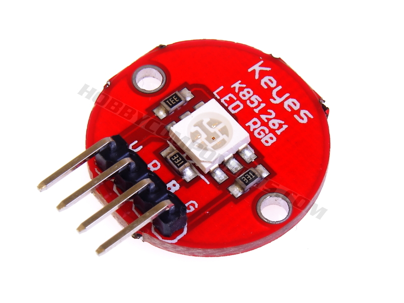

A break-out board for an integrated RGB LED module. The module has 3 separate LED's (Red, Green & Blue) which can be individually driven by applying a voltage to the appropriate module pin. By mixing different colour intensities an almost unlimited range of colours can be created. The module also includes current limiting resistors designed to allow the module to be directly driven from a 5V source. This means that it can be directly connected to the digital pins of a microcontroller.

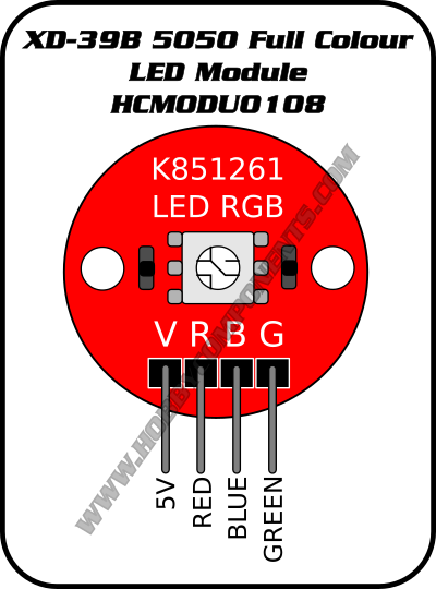
Pinout
Example Arduino Sketch
Code: Select all
/* FILE:    HCMODU0108_RGB_LED_Module_Example
   DATE:    30/08/2016
   VERSION: 0.1

This is a simple example of how to use the Hobby Components RGB LED module
(HCMODU0108). The module has 3 separate LED's (Red, Green & Blue) which
Can be individually driven by applying a voltage to the appropriate module pin.
This example uses the standard Arduino analogWrite (PWM) function to cycle
through the full range of colours this module is capable of producing.


PINOUT:
PIN 1: GREEN LED +Ve
PIN 2: RED LED +Ve
PIN 3: BLUE LED +Ve
PIN 4: GND

You may copy, alter and reuse this code in any way you like, but please leave
reference to HobbyComponents.com in your comments if you redistribute this code.
This software may not be used for the purpose of selling products that directly compete
 with Hobby Components Ltd's own range of products.

THIS SOFTWARE IS PROVIDED "AS IS". HOBBY COMPONENTS MAKES NO WARRANTIES, WHETHER
EXPRESS, IMPLIED OR STATUTORY, INCLUDING, BUT NOT LIMITED TO, IMPLIED WARRANTIES OF
MERCHANTABILITY AND FITNESS FOR A PARTICULAR PURPOSE, ACCURACY OR LACK OF NEGLIGENCE.
HOBBY COMPONENTS SHALL NOT, IN ANY CIRCUMSTANCES, BE LIABLE FOR ANY DAMAGES,
INCLUDING, BUT NOT LIMITED TO, SPECIAL, INCIDENTAL OR CONSEQUENTIAL DAMAGES FOR ANY
REASON WHATSOEVER.

*/


#define BLUE_LED_DIO 11     /* Select the DIO for driving the BLUE LED */
#define RED_LED_DIO 9       /* Select the DIO for driving the RED LED */
#define GREEN_LED_DIO 10    /* Select the DIO for driving the GREEN LED */

/* Initialise serial and DIO */
void setup()
{
  /* Configure the DIO pins used by the analogWrite PWM function  */
  pinMode(BLUE_LED_DIO, OUTPUT);
  pinMode(RED_LED_DIO, OUTPUT);
  pinMode(GREEN_LED_DIO, OUTPUT);
}

/* Main program loop */
void loop()
{
  int k;

  /* Slowly reduce the red LED's intensity and at the same time
     increase the green LED's intensity */
  for (k = 0; k <=255; k++)
  {
    analogWrite(RED_LED_DIO,255 - k);
    analogWrite(GREEN_LED_DIO, k);
    delay(10);
  }

  /* Slowly reduce the green LED's intensity and at the same time
     increase the blue LED's intensity */
  for (k = 0; k <=255; k++)
  {
    analogWrite(GREEN_LED_DIO,255 - k);
    analogWrite(BLUE_LED_DIO, k);
    delay(10);
  }

  /* Slowly reduce the blue LED's intensity and at the same time
     increase the red LED's intensity */
  for (k = 0; k <=255; k++)
  {
    analogWrite(BLUE_LED_DIO,255 - k);
    analogWrite(RED_LED_DIO, k);
    delay(10);
  }
}