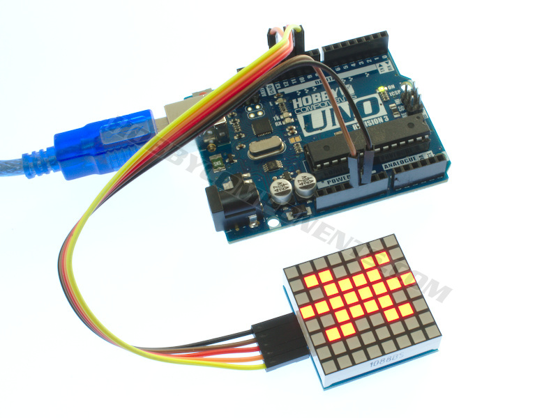

This serial LED dot-matrix module consists of an 8x8 grid of red LEDs. It is based on the Maxim MAX7219 serial LED controller IC which gives the module the ability to not only be programmed via the serial (SPI) interface of a microcontroller, but also allows it to be daisy-chained so that multiple modules can be linked together and controlled with just 3 digital pins (Din, Clk, CS). The driver board for the module does not extend beyond the LED module itself and so multiple modules can be added as both columns and rows without any gaps between each module allowing for much larger displays to be constructed.


For Arduino uses we have also written an exclusive library (HCDisplay) which will help you develop your project with the minimum of effort. This library can be downloaded from the support section of our support forum here:
http://forum.hobbycomponents.com/viewto ... =58&t=2827
Specification:
Product code: HCMODU0135
Interface: Serial (SPI)
Controller: MAX7219
Number of LEDs: 64 (8x8)
LED colour: Red
Voltage: 4.0 - 5.5V
Max current: 370mA (all LEDs on, max brightness)
Min current: <0.5mA (shutdown mode)
Dimensions: 32mm x 32mm x 12mm
Example Arduino Sketch:
- /* FILE: HCDisplay_Dot_Matrix_Hello_World
- DATE: 20/12/18
- VERSION: 0.1
- AUTHOR: Andrew Davies
- 20/12/18 version 0.1: Original version
- This example sketch demonstrates how to use the HCDisplay library to scroll some
- text on the MAX7219 dot matrix display module(s). This sketch supports the following
- displays:
- MAX7219 Serial LED dot matrix module - Red (SKU: HCOPTO0014).
- 8x8 LED Square Dot Matrix Module (Red) (SKU: HCOPTO0014).
- Connect your module(s) to you Arduino as follows:
- MODULE............UNO/NANO
- GND...............GND
- VCC...............5V
- DIN...............11 (MOSI)
- CLK...............13 (SCK)
- CS................10 (SS)
- NOTE: TO USE THIS SKETCH YOU MUST FIRST SELECT THE VERSION OF DISPLAY YOU HAVE BY
- UNCOMMENTING THE APPROPRIATE LINE IN THE OPTIONS.H FILE WHICH CAN BE FOUND IN THE
- HCDISPLAY LIBRARY FOLDER. For windows users avoid using the Windows Notepad editor
- as it doesn't format things properly
- If you have more than one module connected you must tell the sketch what
- configuration you have them connected by changing the values for DRIVERS_X &
- DRIVERS_Y in the sketch below.
- More information about this library can be found in the software section of our
- support forum here:
- http://forum.hobbycomponents.com/software
- You may copy, alter and reuse this code in any way you like, but please leave
- reference to HobbyComponents.com in your comments if you redistribute this code.
- This software may not be used directly for the purpose of selling products that
- directly compete with Hobby Components Ltd's own range of products.
- THIS SOFTWARE IS PROVIDED "AS IS". HOBBY COMPONENTS MAKES NO WARRANTIES, WHETHER
- EXPRESS, IMPLIED OR STATUTORY, INCLUDING, BUT NOT LIMITED TO, IMPLIED WARRANTIES OF
- MERCHANTABILITY AND FITNESS FOR A PARTICULAR PURPOSE, ACCURACY OR LACK OF NEGLIGENCE.
- HOBBY COMPONENTS SHALL NOT, IN ANY CIRCUMSTANCES, BE LIABLE FOR ANY DAMAGES,
- INCLUDING, BUT NOT LIMITED TO, SPECIAL, INCIDENTAL OR CONSEQUENTIAL DAMAGES FOR ANY
- REASON WHATSOEVER. */
- #include "HCDisplay.h"
- /*******************************************************************************************************/
- /**************************************** USER SETTINGS ************************************************/
- /*******************************************************************************************************/
- #define CS 10 //Digital pin used for the modules chip select (CS)
- #define DRIVERS_X 1 //Number of modules daisy-chained in the X direction
- #define DRIVERS_Y 1 //Number of modules daisy-chained in the Y direction
- /*******************************************************************************************************/
- #define RES_X (DRIVERS_X * 8) //Resolution in pixels in the x direction
- uint8_t Buffer[RES_X * DRIVERS_Y]; //Display buffer used by the HCDisplay library
- HCDisplay HCDisplay; //Creates an instance of the HCDisplay library
- void setup()
- {
- HCDisplay.Init(CS, DRIVERS_X, DRIVERS_Y, Buffer); //Initialise the display
- }
- void loop()
- {
- HCDisplay.SetFG(1); HCDisplay.SetBG(0); // Set the foreground and background colours
- ScrollText("Hello World!"); // Print some text
- HCDisplay.SetFG(0); HCDisplay.SetBG(1); // Reverse the foreground and background colours
- ScrollText("HobbyComponents.com"); // Print some text
- }
- /* Scroll some text. Demonstrates the Print() & Pos() functions. */
- void ScrollText(uint8_t *Text)
- {
- int Length = strlen(Text) * 8; // Calculate length of string in pixels.
- // Scroll the text across the display
- for(int x = RES_X; x > -Length; x--)
- {
- HCDisplay.Pos(x, 0);
- HCDisplay.Print(Text);
- delay(50);
- }
- }

The HCDisplay library for the above sketch can be downloaded from the software section of this support forum here:
http://forum.hobbycomponents.com/viewto ... =58&t=2827
Libraries, example code, and diagrams are provided as an additional free service by Hobby Components and are not sold as part of this product. We do no provide any guarantees or warranties as to their accuracy or fitness for purpose.
Descriptions and diagrams on this page are copyright Hobby Components Ltd and may not be reproduced without permission.