Order yours here

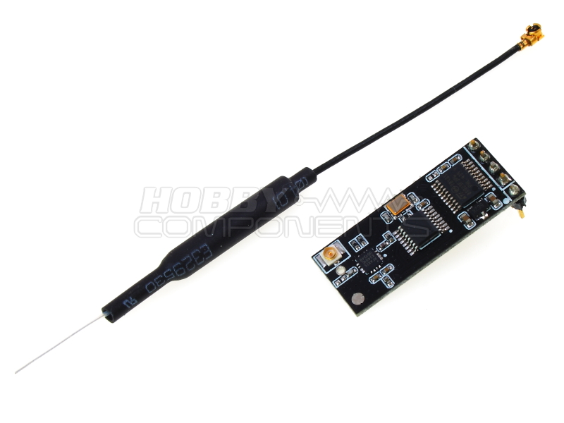
The TB387 high powered module (HCMODU0089) provides a means of transmitting serial data over much greater ranges than standard RF modules such as Bluetooth. Simply connect a TTL serial interface to a transmitter and receiver module and the modules will transparently transmit your data over a 2.4GHz signal at a range of up to 400 meters. In practice we have successfully transmitted single byte data in free air in excess of this. The module can also be placed into a configuration (AT) mode and using simple ASCII 'AT' commands sent via its serial port its default parameters can be changed. This includes changing its frequency to one of 80 channels or its two byte ID which allows a theoretical 65536 modules to communicate with each other. To try and reduce errors caused by poor reception an automatic retry system is enabled (defaults to 100 retries) which will repeatedly resend a data packet a fixed number of times.

Model number: HCMODU0089
Working voltage: 3.3V-5.5V;
Frequency range: 2402~2482MHz
Transmit power: 20dBm;
Receiver sensitivity: -87dBm;
Operating temperature: -40~+85 ° c;
Transparent transmission mode baud rate:
2400, 4800, 9600(Default), 14400, 19200, 38400, 57600, 115200, 12800, 25600
AT mode configured baud rate fix to: 9600;
Transmission current: 120mA peak
Receive current: 30mA
Module dimensions: 32mm (l) x 12.8mm (w) x 11.3 (h including header)
Antenna length: 106mm (inc ufl connector)

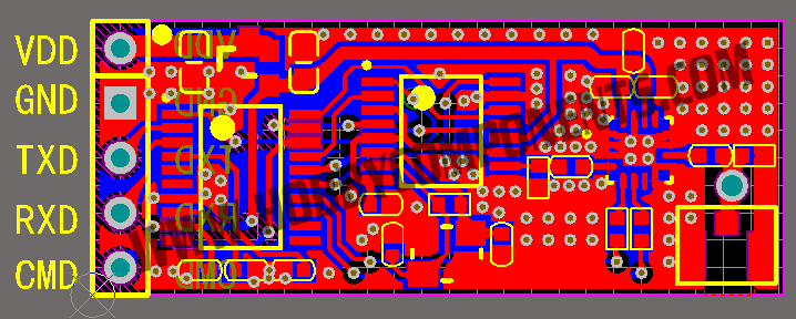
1....VDD: 3.3V or 5V power supply
2....GND: Ground
3....TXD: serial port output, Arduino or USB to serial port RXD
4....RXD: serial port input, Arduino or USB to serial port TXD
5....CMD: Enter PIN AT mode, active low level;
AT Command Mode:
To enter AT mode you must pull the CMD pin low *AFTER* the module has been powered up. AT mode can be entered and left at any point by toggling this pin. To exit AT mode either pull the pin high or leave it floating.
Once in AT mode default BAUD rate is 9600 irrespective of what the BAUD rate is set to.
When sending AT commands a line feed (LF) or carriage return (CR) is not required.
AT Commands:
Change baud rate for communication mode:
AT+BAUD=<BAUD>
Where <BAUD> is one of the following values:
0 = 2400
1 = 4800
2 = 9600
3 = 1440
4 = 19200
5 = 38400
6 = 57600
7 = 115200
8 = 128000
9 = 256000
Note that lower BAUD rates will result in lower transmission errors. Also, be aware that the module has a 32 byte serial buffer. If the receiving module has a lower BAUD rate you should allow time for the receiver to transfer the data.
Change frequency (channel):
AT+FREQ=<FREQ>
Where <FREQ> is the frequency in MHz in addition to the modules base frequency of 2402MHz. E.g.
AT+FREQ=8
Will change the module channel to 2410MHz (2.410GHz). Maximum frequency setting is 2480MHz.
Change the modules ID:
AT+ID=<ID>
Where ID is a two byte identifier giving a theoretical 65536 different identifiers. Modules must have the same ID value to communicate with one another.
Change the number of automatic resends:
AT+RETRY=<VALUE>
Where <VALUE> is the number of retries.
Query the current BAUD rate:
AT+BAUD?
Example response:
BAUD = 2
Query the current frequency:
AT+FREQ?
Example response:
FREQ = 0x27
Query the current ID:
AT+ID?
Example response:
ID = 0x1234
Query the current number of retries:
AT+RETRY?
Example response:
RETRY = 0x64
Query the current software version:
AT+INF
Response:
Thank You For Choosing TB387
Version:2.00
Restore to factory settings:
AT+RESET
Basic Arduino Sketch To Remotely Blink An LED:
Code: Select all
/* FILE: TB387_Transmit_Example.ino
DATE: 24/06/15
VERSION: 0.1
AUTHOR: Andrew Davies
06/07/15 version 0.1: Original version
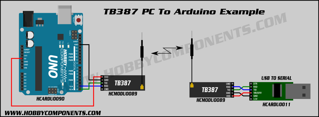
PINOUT:
Module......Arduino
VDD.........5V
GND.........GND
TXD.........Rx
RXD.........Tx
You may copy, alter and reuse this code in any way you like, but please leave
reference to HobbyComponents.com in your comments if you redistribute this code.
This software may not be used directly for the purpose of selling products that
directly compete with Hobby Components Ltd's own range of products.
THIS SOFTWARE IS PROVIDED "AS IS". HOBBY COMPONENTS MAKES NO WARRANTIES, WHETHER
EXPRESS, IMPLIED OR STATUTORY, INCLUDING, BUT NOT LIMITED TO, IMPLIED WARRANTIES OF
MERCHANTABILITY AND FITNESS FOR A PARTICULAR PURPOSE, ACCURACY OR LACK OF NEGLIGENCE.
HOBBY COMPONENTS SHALL NOT, IN ANY CIRCUMSTANCES, BE LIABLE FOR ANY DAMAGES,
INCLUDING, BUT NOT LIMITED TO, SPECIAL, INCIDENTAL OR CONSEQUENTIAL DAMAGES FOR ANY
REASON WHATSOEVER.
*/
void setup()
{
Serial.begin(9600);
}
void loop()
{
/* Send out a 'H' to set the remote LED pin high */
Serial.print("H");
delay(1000);
/* Send out a 'L' to set the remote LED pin low */
Serial.print("L");
delay(1000);
}Code: Select all
/* FILE:    TB387_Receive_Example.ino
   DATE:    24/06/15
   VERSION: 0.1
   AUTHOR:  Andrew Davies

06/07/15 version 0.1: Original version

PINOUT:

Module......Arduino
VDD.........5V
GND.........GND
TXD.........Rx
RXD.........Tx


You may copy, alter and reuse this code in any way you like, but please leave
reference to HobbyComponents.com in your comments if you redistribute this code.
This software may not be used directly for the purpose of selling products that
directly compete with Hobby Components Ltd's own range of products.

THIS SOFTWARE IS PROVIDED "AS IS". HOBBY COMPONENTS MAKES NO WARRANTIES, WHETHER
EXPRESS, IMPLIED OR STATUTORY, INCLUDING, BUT NOT LIMITED TO, IMPLIED WARRANTIES OF
MERCHANTABILITY AND FITNESS FOR A PARTICULAR PURPOSE, ACCURACY OR LACK OF NEGLIGENCE.
HOBBY COMPONENTS SHALL NOT, IN ANY CIRCUMSTANCES, BE LIABLE FOR ANY DAMAGES,
INCLUDING, BUT NOT LIMITED TO, SPECIAL, INCIDENTAL OR CONSEQUENTIAL DAMAGES FOR ANY
REASON WHATSOEVER.
*/

#define LEDPIN 13

void setup()
{
  Serial.begin(9600);
  /* Set the pin that will control the LED to an output. */
  pinMode(LEDPIN, OUTPUT);
}

void loop()
{
  char Data;

  /* Has a byte of data been recived? */
  if (Serial.available() > 0)
  {
    /* If so then get the data */
    Data = Serial.read();

    /* If the received byte is a 'H' then set the LED pin high */
    if (Data == 'H')
      digitalWrite(LEDPIN, HIGH);

    /* If the received byte is a 'L' then set the LED pin low */
    if (Data == 'L')
      digitalWrite(LEDPIN, LOW);
  }
}
FAQ:
What is the range of these modules?
The manufacturer specs the maximum range in open air to be 400 meters. In our own range test we have seen successful transmissions at around 615 meters using single byte data and good weather conditions (see best practices below).
Can I transmit to more than one receiver?
Yes, so long as the receivers are on the same channel and have the same ID then it is theoretically possible to transmit to up to 65534 receivers.
Best practices for getting maximum range
To achieve the best possible range there are several things you can take into consideration:
Lowering the transmission rate (BUAD) of your data - lowering the data rate will reduce the likelihood of packet corruption.
Keep the antenna of the receiver in the same orientation as the transmitter - this will have a significant effect on range.
Keep the antenna away from solid objects, especially metal - RF signals do not like to transmit though solid objects. Nearby metal objects will also de-tune your antenna and reduce its range.
Use a smooth power supply - When transmitting, the module can easily draw 120mA. This can cause momentary dips in your power supply (especially if powering from an Arduino) and in turn can cause the module to be temporally kicked off frequency. If you are having transmission problems even at small distances this could be the cause. Try placing a relatively small capacitor across the modules power supply (e.g. 10uF).
Change the channel - The modules operate on the 2.4GHz frequency spectrum. This frequency range is shared by a lot of modern devices such as WiFi, Bluetooth, wireless cameras etc. The channel you are on may be very busy so try changing the modules channel to a different frequency.
Move the receiver - 2.4GHz signals like to bounce off solid objects. These reflected (multi-path) signals then recombine and can cancel out or multiply with each other to create dead zones and hot spots. Simply moving the receiver slightly may move it out of a possible dead zone.
Disclaimer: Libraries, example code, and diagrams are provided as an additional free service by Hobby Components and are not sold as part of this product. We do not provide any guarantees or warranties as to their accuracy or fitness for purpose.
Descriptions and diagrams on this page are copyright Hobby Components Ltd and may not be reproduced without permission.