AMP2.5 NEO-6M GPS Module (HCMODU0023)
Description:
Cost effective, high-performance u-blox 6 based NEO-6 series of GPS modules, that brings the high performance of the u-blox 6 positioning engine to the miniature
NEO form factor. These receivers combine a high level of integration capability with flexible connectivity options in a small package. This makes them perfectly suited for mass-market end products with strict size and cost requirements.
Easy use via serial interface. No configuration required to use - just connect to the module at 9600 BAUD and module will automatically output GPS information.
You can purchase this module here.
Specification:
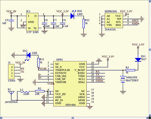
GPS modules NEO-6M, 3.6V-5V Supply Voltage.
Module with ceramic antenna for improved reception.
EEPROM to save the configuration parameters whilst powered down.
LED signal indicator (flashing when valid GPS signal)
With data backup battery
The default baud rate: 9600
Mounting Hole 3mm
Module size 23mm * 30mm
Antenna size : 25mm*25mm
Cable Length: 50mm
Documentation:
(Please log in to download)
You do not have the required permissions to view the files attached to this post.
Re: AMP2.5 NEO-6M GPS Module (HCMODU0023)
Here is some basic code to get you started with the NEO-6M GPS Module
This simply reads the transmitted data from the module and spits out a human readable version on the serial interface.
Code: Select all
Pin connections
Module - Arduino
GND - GND
RX - Pin 11
TX - Pin 10
VCC - 3.3V
Code: Select all
// A simple sketch to read GPS data and parse the $GPRMC string
// see http://www.ladyada.net/make/gpsshield for more info
#include <SoftwareSerial.h>
SoftwareSerial mySerial(10, 11);
#define GPSRATE 9600
//#define GPSRATE 38400
// GPS parser for 406a
#define BUFFSIZ 90 // plenty big
char buffer[BUFFSIZ];
char *parseptr;
char buffidx;
uint8_t hour, minute, second, year, month, date;
uint32_t latitude, longitude;
uint8_t groundspeed, trackangle;
char latdir, longdir;
char status;
void setup()
{
Serial.begin(GPSRATE);
mySerial.begin(GPSRATE);
// prints title with ending line break
Serial.println("GPS parser");
}
void loop()
{
uint32_t tmp;
readline();
// check if $GPRMC (global positioning fixed data)
if (strncmp(buffer, "$GPRMC",6) == 0) {
// hhmmss time data
parseptr = buffer+7;
tmp = parsedecimal(parseptr);
hour = tmp / 10000;
minute = (tmp / 100) % 100;
second = tmp % 100;
parseptr = strchr(parseptr, ',') + 1;
status = parseptr[0];
parseptr += 2;
// grab latitude & long data
// latitude
latitude = parsedecimal(parseptr);
if (latitude != 0) {
latitude *= 10000;
parseptr = strchr(parseptr, '.')+1;
latitude += parsedecimal(parseptr);
}
parseptr = strchr(parseptr, ',') + 1;
// read latitude N/S data
if (parseptr[0] != ',') {
latdir = parseptr[0];
}
// longitude
parseptr = strchr(parseptr, ',')+1;
longitude = parsedecimal(parseptr);
if (longitude != 0) {
longitude *= 10000;
parseptr = strchr(parseptr, '.')+1;
longitude += parsedecimal(parseptr);
}
parseptr = strchr(parseptr, ',')+1;
// read longitude E/W data
if (parseptr[0] != ',') {
longdir = parseptr[0];
}
// groundspeed
parseptr = strchr(parseptr, ',')+1;
groundspeed = parsedecimal(parseptr);
// track angle
parseptr = strchr(parseptr, ',')+1;
trackangle = parsedecimal(parseptr);
// date
parseptr = strchr(parseptr, ',')+1;
tmp = parsedecimal(parseptr);
date = tmp / 10000;
month = (tmp / 100) % 100;
year = tmp % 100;
Serial.print("\nTime: ");
if(hour < 10){Serial.print('0');}
Serial.print(hour, DEC); Serial.print(':');
if(minute < 10){Serial.print('0');}
Serial.print(minute, DEC); Serial.print(':');
if(second < 10){Serial.print('0');}
Serial.println(second, DEC);
Serial.print("Date: ");
if(date < 10){Serial.print('0');}
Serial.print(date, DEC); Serial.print('/');
if(month < 10){Serial.print('0');}
Serial.print(month, DEC); Serial.print('/');
Serial.println(year, DEC);
Serial.print("Lat: ");
if (latdir == 'N')
Serial.print('+');
else if (latdir == 'S')
Serial.print('-');
Serial.print(latitude/1000000, DEC); Serial.write('\°'); Serial.print(' ');
Serial.print((latitude/10000)%100, DEC); Serial.print('\''); Serial.print(' ');
Serial.print((latitude%10000)*6/1000, DEC); Serial.print('.');
Serial.print(((latitude%10000)*6/10)%100, DEC); Serial.println('"');
Serial.print("Long: ");
if (longdir == 'E')
Serial.print('+');
else if (longdir == 'W')
Serial.print('-');
Serial.print(longitude/1000000, DEC); Serial.write('\°'); Serial.print(' ');
Serial.print((longitude/10000)%100, DEC); Serial.print('\''); Serial.print(' ');
Serial.print((longitude%10000)*6/1000, DEC); Serial.print('.');
Serial.print(((longitude%10000)*6/10)%100, DEC); Serial.println('"');
}
//Serial.println(buffer);
}
uint32_t parsedecimal(char *str) {
uint32_t d = 0;
while (str[0] != 0) {
if ((str[0] > '9') || (str[0] < '0'))
return d;
d *= 10;
d += str[0] - '0';
str++;
}
return d;
}
void readline(void) {
char c;
buffidx = 0; // start at begninning
while (1) {
c=mySerial.read();
if (c == -1)
continue;
//Serial.print(c);
if (c == '\n')
continue;
if ((buffidx == BUFFSIZ-1) || (c == '\r')) {
buffer[buffidx] = 0;
return;
}
buffer[buffidx++]= c;
}
}
Re: AMP2.5 NEO-6M GPS Module (HCMODU0023)
Hi
What's the supply voltage range for this module? I can't see it mentioned anywhere and I note that there's a 3.3 V LDO regulator on the board which seems to be a Micrel MIC5205-3.3YM5 which has a very low dropout voltage ~100mV @ 40mA but might still be marginal if I feed it 3.3V. I see the supply voltage for the Ublox unit from the spec sheet but not for the overall PCB.
Just in case before I power it up!
Thanks
John
Re: AMP2.5 NEO-6M GPS Module (HCMODU0023)
The manufacturer specifies the supply range as between 3 to 5V. I'm guessing the are just working on the fact that the minimum working voltage of the module 2.7V + dropout voltage of the regulator. But it's generally not a good idea to use a regulator outside of its operating range as they can become unstable (e.g. they can oscillate or not regulate correctly). I think with 3.3V as it would only just be outside its minimum drop out voltage you may be ok but its not guaranteed. I would say safe ranges would be between 3.5 and 5.5V.
Comments made by this poster do not necessarily reflect the views of Hobby Components Ltd.
Re: AMP2.5 NEO-6M GPS Module (HCMODU0023)
Andrew
As I thought, thanks for the confirmation.
John
As I thought, thanks for the confirmation.
John
Re: AMP2.5 NEO-6M GPS Module (HCMODU0023)
SCHEMATIC DIAGRAM:
Re: AMP2.5 NEO-6M GPS Module (HCMODU0023)
I'm getting nothing from this. Should it at least light up a power LED?
Re: AMP2.5 NEO-6M GPS Module (HCMODU0023)
Yes you should at the very least see a power LED (usually red) light up. If this isn't the case then you need to check your power supply connections. How are you powering it? I.e. what supply voltage and what pins are you connected to?
[Edit 04/03/16] Please note that currently shipped GPS modules do not have a power indicator. The on-board LED functions as a GPS lock indicator and will not illuminate until the module obtains either a partial or full GPS lock.
[Edit 04/03/16] Please note that currently shipped GPS modules do not have a power indicator. The on-board LED functions as a GPS lock indicator and will not illuminate until the module obtains either a partial or full GPS lock.
Last edited by andrew on Fri Mar 04, 2016 1:53 pm, edited 1 time in total.
Comments made by this poster do not necessarily reflect the views of Hobby Components Ltd.
-
- Posts: 3
- Joined: Sat Aug 29, 2015 12:45 pm
Re: AMP2.5 NEO-6M GPS Module (HCMODU0023)
This is a great little GPS module. Sadly the pcb designers forgot to add a 5th pin to the connector for an important feature: The module provides a GPS locked high precision timer output (between 0.25Hz and 1KHz for the NEO-6M) at pin3 (TIMEPULSE). This is ideal for using the module as timebase or frequency standard. You can even program the cable delay if you want a Rubidium Standard like time signal. I added the 5th pin with a little bit of soldering. It is connected to pin3 of the chip - in fact the SMD resistor in front of the LED (see attached image). If you are concerned about pulse rise and fall times you can remove the resistor to get rid of the current drain and capacitive load of the LED at your own risk.
You do not have the required permissions to view the files attached to this post.