Order yours here

This amazingly priced wireless module allows any microcontroller to connect to a 802.11b/g/n wireless network. This in turn provides your microcontroller project with the ability or request data from a server anywhere in the word via a suitable WiFI connection. Control of the module couldn't be simpler as it comes pre-flashed with a serial application allowing it to be controlled via simple 'AT' serial commands.
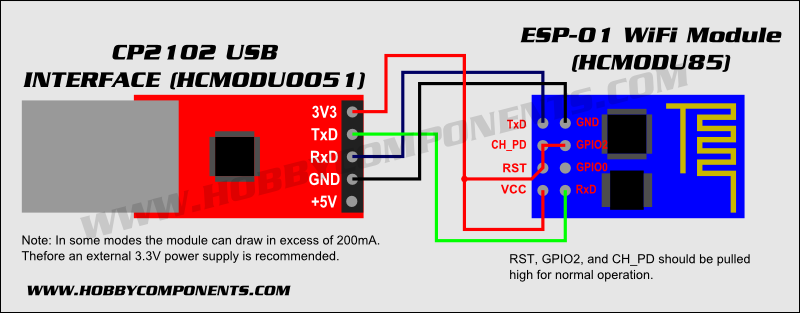
To interface to the module a standard 0.1" pitch 8 pin header is pre-soldered proving access to power, serial, and configuration pins.
Please Note: This module operates at 3.3V only. If interfacing to a 5V microcontroller level sifters should be used.

SKU: HCMODU0085
Module: ESP-01
Device: ESP8266MOD
Frequency: (ISM): 2.4GHz
Power: +25dBm
Supported Wifi: 802.11 b/g/n
Operating voltage: 3.3V
Min Current (Sleep): 10mA
Max current (connected to 802.11b network): 215mA


VCC.........3.3V
GND........0V
CH_PD.....Power down pin. Connect to 3.3V for normal operation
Additionally to configure the module to accept AT commands you should connect the following pins to GND/VCC
CH_PD......VCC (HIGH)
GPIO2......VCC (HIGH)
RST.........VCC (HIGH)
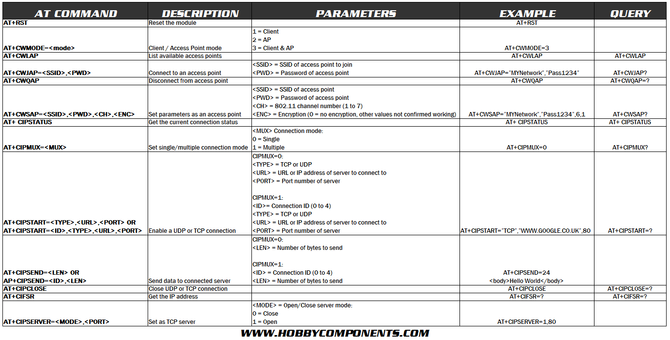
AT Commands:
Default baud rate is 9600 baud (EDIT 07/03/11: Current shipped modules have an updated firmware which now defaults to 115200 BAUD) . All commands must be terminated with both a cartridge return <CR> and line feed <LF>

Example website request:
Open up a serial terminal connection to the module with a baud rate of 9600 BAUD
Reset the module so that it is in a known status:
AT+RST
Response:
OK
ets Jan 8 2013,rst cause:1, boot mode:(3,6)
load 0x40100000, len 1396, room 16
tail 4
chksum 0x89
load 0x3ffe8000, len 776, room 4
tail 4
chksum 0xe8
load 0x3ffe8308, len 540, room 4
tail 8
chksum 0xc0
csum 0xc0
2nd boot version : 1.4(b1)
SPI Speed : 40MHz
SPI Mode : DIO
SPI Flash Size & Map: 8Mbit(512KB+512KB)
jump to run user1 @ 1000
rlŽ‚rlÌÿ
Ai-Thinker Technology Co.,Ltd.
ready
Set the mode to client:
AT+CWMODE=1
Response:
change
List available WiFi networks:
AT+CWLAP
Response:
+CWLAP:(4,"dcoda",-86,"9c:97:26:ce:b3:d9",1)
+CWLAP:(4,"HCWireless",-53,"00:24:a5:bd:10:d4",8)
OK
Connect to your access point:
AT+CWJAP="YOURSSID","YOURPASSWORD"
Respose:
OK
Open a TCP connection to a website:
AT+CIPSTART="TCP","google.co.uk",80
Response:
OK
Linked
Request a page (number of bytes includes a CR & LF):
AT+CIPSEND=30
Response:
>
The '>' signifies that the module is now expecting 30 bytes of data including a CF & LF
Send a GET request for the page:
GET http://www.google.co.uk/
The module will now return the result of the request followed by an OK
Basic Server Example:
Open up a serial terminal connection to the module with a baud rate of 9600 BAUD
Reset the module so that it is in a known state:
AT+RST
Set the mode to both client and access point:
AT+CWMODE=3
The module should now be visible to any wifi client such as a PC, tablet or smart phone with a default SSID of 'ESP_9D66BF' as an open wifi network. Connect to this network with your WiFi client.
Allow multiple connections:
AT+CIPMUX=1
Enable as server accepting connections on port 80:
AT+CIPSERVER=1,80
The default address (gateway) of the module will be 192.168.4.1
Open a browser on your client and go to this address. You should now see your browsers request appear in the terminal window. To send a basic response:
Tell the module we are sending 26 bytes of data (including a CR+LF)
AT+CIPSEND=0,26
Module will responds with a '>'
Send the following:
<body>Hello World</body>
The text hello world should now appear in your clients browser.
Close the connection:
AT+CIPCLOSE=0