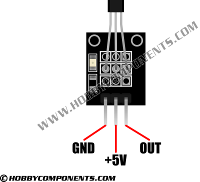
This sensor accepts a GND and +5V supply, and has a single digital output which goes low (GND) when a magnetic field is detected. An on board LED will also indicate the presence of a magnetic field.
Pinout

PIN 1: GND
PIN 2: +5V
PIN 3: OUT
Code: Select all
/* FILE:    ARD_Vibration_Sensor_Module_Example
   DATE:    05/06/13
   VERSION: 0.1

This is a simple example of how to use the Hobby Components hall effect sensor
module.

The sensor accepts a GND and +5V supply, and has a single digital output
which goes low (GND) when a magnetic field is detected.

This example sketch will simply output a message to the UART when it
senses this pin going low.

SENSOR PINOUT:
PIN 1: GND
PIN 2: +5V
PIN 3: DATA OUT

You may copy, alter and reuse this code in any way you like, but please leave
reference to HobbyComponents.com in your comments if you redistribute this code.
This software may not be used directly for the purpose of selling products that
directly compete with Hobby Components Ltd's own range of products.

THIS SOFTWARE IS PROVIDED "AS IS". HOBBY COMPONENTS MAKES NO WARRANTIES, WHETHER
EXPRESS, IMPLIED OR STATUTORY, INCLUDING, BUT NOT LIMITED TO, IMPLIED WARRANTIES OF
MERCHANTABILITY AND FITNESS FOR A PARTICULAR PURPOSE, ACCURACY OR LACK OF NEGLIGENCE.
HOBBY COMPONENTS SHALL NOT, IN ANY CIRCUMSTANCES, BE LIABLE FOR ANY DAMAGES,
INCLUDING, BUT NOT LIMITED TO, SPECIAL, INCIDENTAL OR CONSEQUENTIAL DAMAGES FOR ANY
REASON WHATSOEVER.

*/

/* Select the input pin for the hall effect sensors output. */
#define HALL_SENSOR_DIO 2


/* Initialise serial and DIO */
void setup()
{
  /* Setup the serial port for displaying the status of the sensor */
  Serial.begin(9600);

  /* Configure the DIO pin which the sensors digital output will be connected to */
  pinMode(HALL_SENSOR_DIO, INPUT);
}


/* Main program loop */
void loop()
{
  /* Read the status of the sensors digital output and if it is low
     then send an alert to the serial port */
  if (!digitalRead(HALL_SENSOR_DIO))
  {
    Serial.println("MAGNETIC FIELD DETECTED!");
  }
}