Page 1 of 2
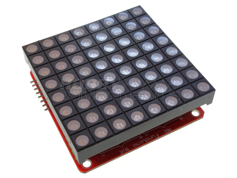
Colorduino RGB matrix development board (HCDVBD0015)
Posted: Thu Jul 17, 2014 1:07 pm
by admin

 Description:
This Arduino compatible board is specifically designed to drive a 3 colour RGB LED dot matrix displays and uses an ATmega328p device loaded with the Arduino bootloader. This allows the development board to be programmed directly from the Arduino development environment (via a suitable TTL serial adaptor). A constant current LED driver provides a PWM hardware interface to to an attached LED module. Designed to be used in conjunction with our RGB LED matrix module (HCMODU0053), this will allow display of any full colour (24bit) 8x8 pattern. To aid in writing your own sketches we have also created our own library which will allow you control the display including scrolling of text and numbers with the minimum of effort.
Besides priding header sockets for the RGB LED module, there are additional interfaces for serial and I2C which allow for programming the board via the freely available Arduino development environment and are arranged in a way so that multiple development boards can be 'daisy-chained' to make up larger displays.
Features:
Full 24bit RGB colour control with 6 bit colour correction
Includes hardware constant current PWM driver
Serial and I2C interfaces allowing for daisy-chaining of additional modules
Specifications:
PCB size: 60mm X 60mm
Microprocessor: Atmega328P
Power supply: 5V
Program interface: UART/ISP
Communication protocols UART/I2C
Example Sketch:
Code: Select all
/* FILE:    Hello_World.cpp
   DATE:    16/07/14
   VERSION: 0.1
   AUTHOR:  Andrew Davies

This is a basic example of how to use the ColourDuino module (HCDVBD0015 & HCMODU0053)
together with the HCColorDuino library to display a simple scrolling text message.

You may copy, alter and reuse this code in any way you like, but please leave
reference to HobbyComponents.com in your comments if you redistribute this code.
This software may not be used directly for the purpose of selling products that
directly compete with Hobby Components Ltd's own range of products.

THIS SOFTWARE IS PROVIDED "AS IS". HOBBY COMPONENTS MAKES NO WARRANTIES, WHETHER
EXPRESS, IMPLIED OR STATUTORY, INCLUDING, BUT NOT LIMITED TO, IMPLIED WARRANTIES OF
MERCHANTABILITY AND FITNESS FOR A PARTICULAR PURPOSE, ACCURACY OR LACK OF NEGLIGENCE.
HOBBY COMPONENTS SHALL NOT, IN ANY CIRCUMSTANCES, BE LIABLE FOR ANY DAMAGES,
INCLUDING, BUT NOT LIMITED TO, SPECIAL, INCIDENTAL OR CONSEQUENTIAL DAMAGES FOR ANY
REASON WHATSOEVER.
*/

/* Include the HCColorDuino library */
#include "HCColorDuino.h"

/* Create an instance of the library */
HCColorDuino HCColorDuino;

void setup()
{
  /* Calibrate the LED matrix display for differences in RGB luminace */
  HCColorDuino.RGBColourCorrection(25, 63, 63);
  /* Set the RGB colour of the font. Valid values are from 0 to 255 for
     each colour */
  HCColorDuino.SetFontFG(0,0,255);

  /* Set the RGB colour of the fonts background. */
  HCColorDuino.SetFontBG(10,0,0);

  /* Turn on continuous auto-scrolling. Scroll from position 0 to 111
     at a scroll speed of 230 (255 max) */
  HCColorDuino.ScrollOn(0, 111, 230, CONTINUOUS);
}

/* Main program */
void loop()
{
  /* Write some text to the character buffer */
  HCColorDuino.print("HELLO WORLD!");
  while(1)
  {
    /* Continuously refresh the the LED matrix */
    HCColorDuino.Refresh();
    delay(1);
  }
}
Code: Select all
/* FILE:    Hello_World_Using_HCTimer2.cpp
   DATE:    16/07/14
   VERSION: 0.1
   AUTHOR:  Andrew Davies

   16/07/14 version 0.1: Original version
   27/11/17 version 0.2: Moved HCColorDuino.print() function into setup() and removed
                         while(1) from main loop as it was being optimised out.

This is a basic example of how to use the ColourDuino module (HCDVBD0015 & HCMODU0053)
together with the HCColorDuino and HCTimer2 library to display a simple scrolling text
message. By using the HCTimer2 library the hardware timer 2 can be re-tasked to refresh
the matrix display in the background.

You may copy, alter and reuse this code in any way you like, but please leave
reference to HobbyComponents.com in your comments if you redistribute this code.
This software may not be used directly for the purpose of selling products that
directly compete with Hobby Components Ltd's own range of products.

THIS SOFTWARE IS PROVIDED "AS IS". HOBBY COMPONENTS MAKES NO WARRANTIES, WHETHER
EXPRESS, IMPLIED OR STATUTORY, INCLUDING, BUT NOT LIMITED TO, IMPLIED WARRANTIES OF
MERCHANTABILITY AND FITNESS FOR A PARTICULAR PURPOSE, ACCURACY OR LACK OF NEGLIGENCE.
HOBBY COMPONENTS SHALL NOT, IN ANY CIRCUMSTANCES, BE LIABLE FOR ANY DAMAGES,
INCLUDING, BUT NOT LIMITED TO, SPECIAL, INCIDENTAL OR CONSEQUENTIAL DAMAGES FOR ANY
REASON WHATSOEVER.
*/

/* Include the HCTimer2 library */
#include <HCTimer2.h>

/* Include the HCColorDuino library */
#include "HCColorDuino.h"

/* Create an instance of the library */
HCColorDuino HCColorDuino;


void setup()
{
  /* Initialise the HCTimer2 library with a 2.4mS interval */
  HCTimer2Init(T2_CLK_DIV_256, 150);

  /* Calibrate the LED matrix display for differences in RGB luminace */
  HCColorDuino.RGBColourCorrection(25, 63, 63);

  /* Set the RGB colour of the font. Valid values are from 0 to 255 for
     each colour */
  HCColorDuino.SetFontFG(0,0,255);

  /* Set the RGB colour of the fonts background. */
  HCColorDuino.SetFontBG(10,0,0);

  /* Turn on continuous auto-scrolling. Scroll from position 0 to 111
     at a scroll speed of 230 (255 max) */
  HCColorDuino.ScrollOn(0, 111, 230, CONTINUOUS);

  /* Display some text */
  HCColorDuino.print("HELLO WORLD!");

}

/* Main program */
void loop()
{
    // Put your own code in here !
}


/* Refresh the matrix display in the background */
void HCTimer2()
{
    HCColorDuino.Refresh();
}
HCTimer2 library (required for some of the example sketches):
http://forum.hobbycomponents.com/viewto ... =43&t=1336
Schematic and datasheet:
Colorduino_Schematic.pdf
DM163_Datasheet.pdf
Order Yours Here.
Re: Colorduino RGB matrix development board (HCDVBD0015)
Posted: Sun Apr 10, 2016 6:57 am
by Berto
admin wrote: ...multiple development boards can be 'daisy-chained' to make up larger displays...
Looking at the schematic, the TXD line passes through the module from previous to next, as well as to the CPU on each module, IE; they are "multi-dropped".
If fact, it's not really "Daisy-Chained" at all (except physically), since no input pin goes through any electronics on the module before being routed to the output pin...
So, anyway, I wonder:-
* What stops multiple CPUs trying to drive the TXD line to conflicting levels?
* I haven't looked at I2C for a long time, but as I recall, it's designed to be multi-dropped, so no problem?
* In either case, how would addressing of a particular module be handled?
The schematic does not clarify the switch position labels.
* Which is +7.5v on Vin going to the regulator, and which is +5v (VDD5) supplied from the daisy-chain? "Terminal" or "Header"?
* Again, being multi-dropped, minor regulator output variations will be in conflict. Too small to worry?
Furthermore, it would seem that the above issues mean that firmware updates cannot be performed while a module is in the chain?
Re: Colorduino RGB matrix development board (HCDVBD0015)
Posted: Mon Apr 11, 2016 8:02 am
by andrew
* What stops multiple CPUs trying to drive the TXD line to conflicting levels?
Nothing physically but just don't write your sketch(s) to output data on the serial pins at the same time.
* I haven't looked at I2C for a long time, but as I recall, it's designed to be multi-dropped, so no problem?
Yes you can have multiple devices on the same I2C bus. If you have several you may need additional pullup resistors.
* In either case, how would addressing of a particular module be handled?
I wouldn't recommend using the serial interface for communicating between multiple boards. For the I2C you would do this in software.
Which is +7.5v on Vin going to the regulator, and which is +5v (VDD5) supplied from the daisy-chain? "Terminal" or "Header"?
The switch is used to decide how you wish to power the modules. It effectively switches out the regulator so in the 'Terminal' position you would power the module via the screw terminal with a supply voltage > 7.5V. In the header position the regulator is switched out so you must power it via an external 5V supply source.
* Again, being multi-dropped, minor regulator output variations will be in conflict. Too small to worry?
Yes I wouldn't personally advise using the internal regulators when connecting multiple boards as the regulators won't be balanced. You'd need to put the power selector switch into the 'Header' position and use an external 5V supply. This is what I assume the power selector switch is actually for.
Furthermore, it would seem that the above issues mean that firmware updates cannot be performed while a module is in the chain?
No, you cant program boards in parallel.
Re: Colorduino RGB matrix development board (HCDVBD0015)
Posted: Tue Apr 12, 2016 8:41 pm
by Berto
Hi Andrew,
Thanks for the quick reply.
(I understood what the switch does, it just wasn't clear to me which position was which. as I found the labels "terminal" and "header" a little vague. But you've cleared it up for me now, thanks)
I notice the latest design for these things has dropped the switch, but kept the regulator. So presumably it's in permanent "terminal" position. Or better yet, maybe they've done what they should have done in the first place: Power the M54564FP anode driver from the screw terminal VIN, and also run the regulator from that to power the remaining chips, leaving VDD off the header.
I think that your suggestion that multiple modules should be powered from an external 5V supply might get a bit problematic with more than just a few modules, as the current requirement will become substantial, along with the voltage drop issues.
When I do this, I think I'll try running separate wires to the screw terminals from each module (or small group thereof) to a largish 7.5v supply.
I'd love to find someone who'd pay me to make an 8x8 matrix of these units!
And then there's the intercommunication scenario involved with that (OMG)...
It would be very important for the applications I envision that the firmware be updatable in-situ (not all in parallel, but individually one after the other). So I guess I2C would be used for normal inter-module communication, but the firmware changes would require a smarter bootloader capable of individual addressing in a multidrop environment along with a protocol to operate on a shared TXD line
I think I'm going to be busy...
Cheers,
Rob
Re: Colorduino RGB matrix development board (HCDVBD0015)
Posted: Sat Nov 25, 2017 7:41 pm
by jasiel
Greetings!
"Hello_World.cpp" for me worked perfectly but "Hello_World_Using_HCTimer2" did not light anything in the Matrix;
I would also like to know how to link several Colorduino together to display text; Thanks for the code
Re: Colorduino RGB matrix development board (HCDVBD0015)
Posted: Sat Nov 25, 2017 8:01 pm
by jasiel
Greetings!
"Hello_World.cpp" for me worked perfectly but "Hello_World_Using_HCTimer2" did not light anything in the Matrix;
I would also like to know how to link several Colorduino together to display text; Thanks for the code
Re: Colorduino RGB matrix development board (HCDVBD0015)
Posted: Sat Nov 25, 2017 8:02 pm
by jasiel
Greetings!
"Hello_World.cpp" for me worked perfectly but "Hello_World_Using_HCTimer2" did not light anything in the Matrix;
I would also like to know how to link several Colorduino together to display text; Thanks for the code
Re: Colorduino RGB matrix development board (HCDVBD0015)
Posted: Sat Nov 25, 2017 8:21 pm
by jasiel
Greetings!
"Hello_World.cpp" for me worked perfectly but "Hello_World_Using_HCTimer2" did not light anything in the Matrix;
I would also like to know how to link several Colorduino together to display text; Thanks for the code