
The Arduino Pro Mini is a microcontroller board based on the ATmega328. It has 14 digital input/output pins (of which 6 can be used as PWM outputs), 6 analog inputs, an on-board resonator, a reset button, and holes for mounting pin headers. A six pin header can be connected to an FTDI cable to provide USB power and communication to the board.
The Arduino Pro Mini is intended for semi-permanent installation in objects or exhibitions. The board comes without pre-mounted headers, allowing the use of various types of connectors or direct soldering of wires. The pin layout is compatible with the Arduino Mini.
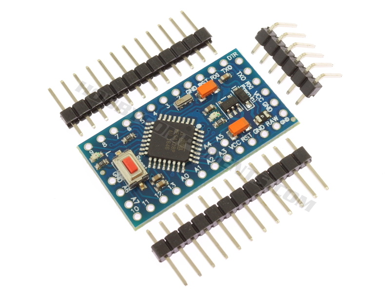
We currently sell two versions of this board, a 5V/16MHz version (HCARDU0059) as pictured above, and a 3.3V/8MHz version (HCARDU0081).
Summary 5V Version
Microcontroller: ATmega328
Operating Voltage: 5V
Input Voltage: 5 - 12 V
Digital I/O Pins: 14 (of which 6 provide PWM output)
Analog Input Pins: 6
DC Current per I/O Pin: 40 mA
Flash Memory: 32 KB (of which 2 KB used by bootloader)
SRAM: 2 KB
EEPROM: 1 KB
Clock Speed: 16 MHz
Summary 3.3V Version
Microcontroller: ATmega328
Operating Voltage: 3.3V
Input Voltage: 5 - 9.6 V
Digital I/O Pins: 14 (of which 6 provide PWM output)
Analog Input Pins: 6
DC Current per I/O Pin: 40 mA
Flash Memory: 32 KB (of which 2 KB used by bootloader)
SRAM: 2 KB
EEPROM: 1 KB
Clock Speed: 8MHz


Please note that this diagram currently contains an error for the SPI interface. The alternate function for pin ADC4 is SDA not SCL. Thanks to oe1gca for pointing this out.
PDF Version (Full Size): Order Links:
5V Pro Mini
[url=http://hobbycomponents.com/boards/385-a ... o-mini3.3V Pro Mini[/url]