
Arduino Library for the PCA9685 16 Channel 12-bit PWM Servo Motor Driver.
Currently supported products:
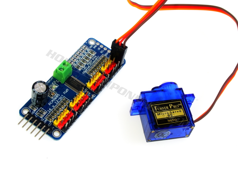
16 Channel 12-bit PWM Servo Motor Driver Module (HCMODU0097) available from hobbycomponents.com
This library can be used to configure and control the NXP semiconductors PCA9685 16 channel 12 bit PWM controller. Additionally the library can initialised into a 'servo mode' which configures the device to produce PWM outputs that are compatible with those required to control a standard servo(s). Each servos position can then be controlled with just one library command.
You will need to download (please log in to download the library) and unzip this library to the Arduino development environments library area.
On Windows:
My Documents\Arduino\libraries\
On Mac:
Documents/Arduino/libraries/
Linux:
Usually found within the users home area under /Arduino/libraries/
Using the HCPCA9685 library
To use the library just include the HCPCA9685.h header file and then create an instance of the library. E.g:
Code: Select all
#include "HCPCA9685.h"
HCPCA9685 HCPCA9685(I2CAdd);
Where I2CAdd is the I2C slave address of the device. The PCA9685, and our module via jumper pads, can be set to one of 62 different slave addresses. For the HCMODU0097 the default address is 0x40.
To initialise the library add the following line to the setup() section of your sketch:
Code: Select all
HCPCA9685.Init();Code: Select all
HCPCA9685.Sleep(false);The following functions are available with this library:
Code: Select all
HCPCA9685.Init(Mode);Mode is the operating mode of the library. Passing no parameter, or passing the value DEFAULT_MODE will initialise the device into a default mode of operation. Use this mode if you want to use the device as a general purpose PWM controller.
Passing SERVO_MODE for the Mode parameter will initialise the library to produce PWM signals that are compatible with driving standard servo(s). Use this mode if you wish to use the device for driving servos.
Code: Select all
HCPCA9685.Sleep(Mode);Mode is the required state. Valid values are:
true puts the device to sleep)
false brings the device out of sleep mode)
If the device is woken up from a previously set sleep state then this function will wait 500us for the oscillator to stabilise.
Code: Select all
HCPCA9685.SetPeriodFreq(Freq);Freq is the required frequency of on cycle. Valid values are:
24 (24Hz) to 1526 (1.526KHz)
These values are based on the devices internal 25MHz oscillator (default). If using an external clock you will need to adjust the value for OSC_FREQ found in the HCPCA9685.h header file.
Code: Select all
HCPCA9685.SetPreScaller(Period);Sets the value for the prescaller where:
Period is the required period for one cycle. Valid values are:
0x03 to 0xFF
The prescaller value can be determined with the following formula: prescale value = (25MHz / (4096 * period frequency in Hz)) - 1
Code: Select all
HCPCA9685.Servo(Chan, Pos);Chan is the PWM output pin to change. Valid values are
0 (PWM output pin 0) to 15 (PWM output pin 15)
Pos is the required position of the servo. Valid values are
0 (servo fully anti-clockwise) to 480 (servo fully clockwise)
The maximum value is based in the default servo SERVO_TRIM_MAX and SERVO_TRIM_MIN trim settings found in the HCPCA9685.h header file. These default to 590 for SERVO_TRIM_MAX and 110 for SERVO_TRIM_MIN. They can be adjusted to match the minimum and maximum end-stop positions for your servo(s). If these values are changed then the new max value for Pos can be calculated as (SERVO_TRIM_MAX - SERVO_TRIM_MIN).
Code: Select all
HCPCA9685.Output(On_Time, Off_Time);On_Time is the point at which to turn the outputs ON within the cycle period. Valid values are
0 to 4095 (decimal)
Off_Time is the point at which to turn the outputs OFF within the cycle period. Valid values are
0 to 4095 (decimal)
Code: Select all
HCPCA9685.Output(Chan, On_Time, Off_Time);Chan is the PWM output pin to change. Valid values are
0 (PWM output pin 0) to 15 (PWM output pin 15)
On_Time is the point at which to turn the output ON within the cycle period. Valid values are
0 to 4095 (decimal)
Off_Time is the point at which to turn the output OFF within the cycle period. Valid values are
0 to 4095 (decimal)
Code: Select all
HCPCA9685.OutputOnTime(Chan, Time);Chan is the PWM output pin to change. Valid values are
0 (PWM output pin 0) to 15 (PWM output pin 15)
Time is the point at which to turn the output on within the cycle period. Valid values are
0 to 4095 (decimal)
Code: Select all
HCPCA9685.OutputOffTime(Chan, Time);Sets the turn OFF time for one of the 15 PWM outputs where:
Chan is the PWM output channel pin to change. Valid values are
0 (PWM output pin 0) to 15 (PWM output pin 15)
Time is the point at which to turn the output off within the cycle period. Valid values are
0 to 4095 (decimal)
Code: Select all
HCPCA9685.OutputNotEnableState(State);State is the required state of the output pins. Valid values are:
OUTNE_LOW Output pins are pulled low when OE = 1
OUTNE_HIGH Output pins are pulled high when OE = 1
OUTNE_HIGH_IMPEDANCE Output pins are high-impedance when OE = 1
Code: Select all
HCPCA9685.OutputDrivers(Mode);Mode is the required type. Valid values are:
OUTDRV_OPEN_DRAIN The 16 PWM outputs are configured with an open-drain structure.
OUTDRV_TOTEM_POLE The 16 PWM outputs are configured with a totem pole structure.
Code: Select all
HCPCA9685.OCH(Mode);Mode is the required state. Valid values are:
OCH_STOP Outputs change on I2C STOP command.
OCH_ACK Outputs change on I2C ACK.
Code: Select all
HCPCA9685.Invert(Mode);Mode is the require state. Valid values are:
false The PWM output pins are not inverted.
true The PWM output pins are inverted.
Code: Select all
HCPCA9685.Enable_Sub1(Mode);Mode sets the required state. Valid values are:
false The device will not respond to I2C sub address 1.
true The device will respond to I2C sub address 1.
Code: Select all
HCPCA9685.Enable_Sub2(Mode);Mode sets the required state. Valid values are:
false The device will not respond to I2C sub address 2.
true The device will respond to I2C sub address 2.
Code: Select all
HCPCA9685.Enable_Sub3(Mode);Mode sets the required state. Valid values are:
false The device will not respond to I2C sub address 3.
true The device will respond to I2C sub address 3.
Code: Select all
HCPCA9685.Enable_AllCall(Mode);Mode sets the required state. Valid values are:
false The device will not respond to I2C ALLCALL address.
true The device will respond to I2C ALLCALL address.
Code: Select all
HCPCA9685.SetSubAddress(SubAddress, Address);SubAddress is one of the 3 sub addresses to set the I2C address for. Valid values are:
SUBADR1 Selects sub address 1.
SUBADR2 Selects sub address 2.
SUBADR3 Selects sub address 3.
Address is and 8 bit byte representing the I2C address to set the selected sub address too. Only the 7 LSBs representing the I2C-bus sub address are valid.
Code: Select all
HCPCA9685.SetAllCallAddress(Address);Address is and 8 bit byte representing the I2C address to set the ALLCALL address too. Only the 7 LSBs representing the I2C-bus ALLCALL address are valid.
Code: Select all
HCPCA9685.ExtClk();Sets external clock mode allowing the device to be driven by an external clock source. When in external clock mode, it can only be cleared by recycling the power.
Code: Select all
HCPCA9685.I2CWriteReg(Register, Data);Register is the address of the register to write to.
Data is the 8 bit data to write to the register.
Code: Select all
byte Data = HCPCA9685.I2CReadReg(Register);Register is the address of the register to read from.
Returns an 8 bit byte containing the contents of the specified register.

- /* FILE: HCPCA9685_Servo_Example
- DATE: 10/06/16
- VERSION: 0.1
- AUTHOR: Andrew Davies
- Sketch created by Hobby Components Ltd (HOBBYCOMPONENTS.COM)
- 10/06/16 version 0.1: Original version
- This example demonstrates how to use the HCPCA9685 library together with the PCA9685
- to control up to 16 servos. The sketch will initialise the library putting it into
- 'servo mode' and then will continuously sweep one servo connected to PWM output 0
- back and forth. The example has been written particularly for the 16 Channel 12-bit
- PWM Servo Motor Driver Module (HCMODU0097) available from hobbycomponents.com
- To use the module connect it to your Arduino as follows:
- PCA9685...........Uno/Nano
- GND...............GND
- OE................N/A
- SCL...............A5
- SDA...............A4
- VCC...............5V
- External 5V Power for the servo(s) can be supplied by the V+ and GND input of the
- screw terminal block.
- PLEASE NOTE: Depending on your servo it is possible for this sketch to attempt
- drive the servo beyond its end stops. If your servo is hitting its end stops then
- you should adjust the the min and max values in this sketch.
- You may copy, alter and reuse this code in any way you like, but please leave
- reference to HobbyComponents.com in your comments if you redistribute this code.
- This software may not be used directly for the purpose of selling products that
- directly compete with Hobby Components Ltd's own range of products.
- THIS SOFTWARE IS PROVIDED "AS IS". HOBBY COMPONENTS MAKES NO WARRANTIES, WHETHER
- EXPRESS, IMPLIED OR STATUTORY, INCLUDING, BUT NOT LIMITED TO, IMPLIED WARRANTIES OF
- MERCHANTABILITY AND FITNESS FOR A PARTICULAR PURPOSE, ACCURACY OR LACK OF NEGLIGENCE.
- HOBBY COMPONENTS SHALL NOT, IN ANY CIRCUMSTANCES, BE LIABLE FOR ANY DAMAGES,
- INCLUDING, BUT NOT LIMITED TO, SPECIAL, INCIDENTAL OR CONSEQUENTIAL DAMAGES FOR ANY
- REASON WHATSOEVER.
- */
- /* Include the HCPCA9685 library */
- #include "HCPCA9685.h"
- /* I2C slave address for the device/module. For the HCMODU0097 the default I2C address
- is 0x40 */
- #define I2CAdd 0x40
- /* Create an instance of the library */
- HCPCA9685 HCPCA9685(I2CAdd);
- void setup()
- {
- /* Initialise the library and set it to 'servo mode' */
- HCPCA9685.Init(SERVO_MODE);
- /* Wake the device up */
- HCPCA9685.Sleep(false);
- }
- void loop()
- {
- unsigned int Pos;
- /* Sweep the servo back and forth from its minimum to maximum position.
- If your servo is hitting its end stops then you should adjust the
- values so that the servo can sweep though its full range without hitting
- the end stops. You can adjust the min & max positions by altering
- the trim values in the libraries HCPCA9685.h file*/
- for(Pos = 10; Pos < 450; Pos++)
- {
- /* This function sets the servos position. It takes two parameters,
- * the first is the servo to control, and the second is the servo
- * position. */
- HCPCA9685.Servo(0, Pos);
- delay(10);
- }
- for(Pos = 450; Pos >= 10; Pos--)
- {
- HCPCA9685.Servo(0, Pos);
- delay(10);
- }
- }
