
This Arduino library (current only supports ATMega328p based Arduinos) will allow you to control one or more DC or stepper motors from you Arduino. The library makes use of the Arduinos hardware interrupt timer 2 to drive the motors in the background leaving your sketch totally free for you main program. It also allows you to mix motor types and connect them to any available digital pins (you are not limited to just PWM pins). You can simply add motors by using the libraries 'Attach' function and remove them using the 'Detach' command. You can also mix supported motor types. Current supported motor types are as follows:
DCMOTOR - A standard DC type motor driven via a transistor or driver module.
DCMOTOR_H_BRIDGE - A standard DC motor connected via a H-Bridge driver module allowing for forward and reverse directions.
STEPPER - A stepper motor connected via a standard stepper motor driver (Step/CLK & Direction)
You will need to download (please log in to download the library) and unzip this library to the Arduino development environments library area.
On Windows:
My Documents\Arduino\libraries\
On Mac:
Documents/Arduino/libraries/
or similarly for Linux.
Changing the maximum number or motors:
By default this library can drive up to 4 motors. However this can be increased by editing the following line in the libraries HCMotor.h file:
Code: Select all
#define MAXMOTORS 4If you are using less than 4 motors and your sketch is processor intensive you may also want to reduce this value to match the number of motors you have attached as this will free up processing cycles for your main loop.
Using the library
To use the library just include the HCMotor.h header file and then create an instance of the library. E.g:
Code: Select all
#include <HCMotor.h>
HCMotor HCMotor;
To initialise the library place the following line in the Setup() loop at the top of the sketch:
Code: Select all
HCMotor.Init();The following functions are available with this library:
Code: Select all
HCMotor.Attach(MotorNum, MotorType, Pin);MotorNum is a value used to reference which motor you wish to attach. Valid values are between 0 and MAXMOTORS. Default maximum is 4.
MotorType is the type of motor being attached. Currently only one valid value (DCMOTOR see alternate version below for other motor types)
Pin is the digital pin to attach it to (this can be any digital pin, not just the hardware PWM pins)
Code: Select all
HCMotor.Attach(MotorNum, MotorType, PinA, PinB);MotorNum is a value used to reference which motor we wish to attach. Valid values are between 0 and MAXMOTORS. Default maximum is 4.
MotorType is the type of motor being attached. Valid values are DCMOTOR_H_BRIDGE or STEPPER
PinA PinB are the digital pins to attach it to. For a stepper motor PinA is the clock pin and PinB is the direction pin.
Code: Select all
HCMotor.detach(MotorNum);Code: Select all
HCMotor.OnTime(MotorNum, Time);MotorNum is a value used to reference which motor we wish to alter.
Time is the amount of the duty cycle the motor will be on for in 100uS increments.
Note that for steppe motors the function does nothing.
Code: Select all
HCMotor.DutyCycle(MotorNum, Time);MotorNum is a value used to reference which motor we wish to alter.
Time is the duty cycle time in uS. For stepper motors this sets the clock speed.
Code: Select all
HCMotor.Direction(MotorNum, Direction);MotorNum is a value used to reference which motor we wish to alter.
Direction is the direction of the motor. Valid values are FORWARD & REVERSE
For H-Bridge motors this will switch the pin the PWM is output to and the sets the opposite pin low.
For stepper motors the will set the direction pin (PinB) high or low.
Code: Select all
HCMotor.Steps(MotorNum, Steps);MotorNum is a value used to reference which motor we wish to alter.
Steps is the number of steps to step the motor.
Note that for DC motors this function does nothing.

DC Motor Example
Code: Select all
/* FILE: HCMotor_DC_Motor_Example
DATE: 09/07/15
VERSION: 0.1
AUTHOR: Andrew Davies
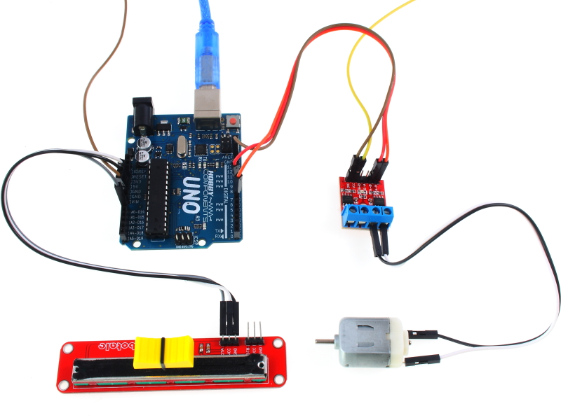
This example uses the library to control a DC motor via a potentiometer connected
analogue pin A0. The motor should be connected to digital pin 7 on the Arduino
via a suitable transistor/driver module. Do not connect the motor directly as you
may damage your Arduino.
You may copy, alter and reuse this code in any way you like, but please leave
reference to HobbyComponents.com in your comments if you redistribute this code.
This software may not be used directly for the purpose of selling products that
directly compete with Hobby Components Ltd's own range of products.
THIS SOFTWARE IS PROVIDED "AS IS". HOBBY COMPONENTS MAKES NO WARRANTIES, WHETHER
EXPRESS, IMPLIED OR STATUTORY, INCLUDING, BUT NOT LIMITED TO, IMPLIED WARRANTIES OF
MERCHANTABILITY AND FITNESS FOR A PARTICULAR PURPOSE, ACCURACY OR LACK OF NEGLIGENCE.
HOBBY COMPONENTS SHALL NOT, IN ANY CIRCUMSTANCES, BE LIABLE FOR ANY DAMAGES,
INCLUDING, BUT NOT LIMITED TO, SPECIAL, INCIDENTAL OR CONSEQUENTIAL DAMAGES FOR ANY
REASON WHATSOEVER.
*/
/* Include the library */
#include "HCMotor.h"
/* Set the pin that will control the motor. Note that it doesn't have to be a PWM pin -
any digital pin will do! */
#define MOTOR_PIN 7
/* Set the analogue pin the potentiometer will be connected to. */
#define POT_PIN A0
/* Create an instance of the library */
HCMotor HCMotor;
void setup()
{
/* Initialise the library */
HCMotor.Init();
/* Attach motor 0 to digital pin 7. The first parameter specifies the
motor number, the second is the motor type, and the third is the
digital pin that will control the motor */
HCMotor.attach(0, DCMOTOR, MOTOR_PIN);
/* Set the duty cycle of the PWM signal in 100uS increments.
Here 100 x 100uS = 1mS duty cycle. */
HCMotor.DutyCycle(0, 100);
}
void loop()
{
int Speed;
/* Read the analogue pin to determine the position of the pot. The map
function takes this value which could be anywhere between 0 - 1024
and reduces it down to match the duty cycle range of 0 - 100 */
Speed = map(analogRead(POT_PIN), 0, 1024, 0, 100);
/* Set the on time of the duty cycle to match the position of the pot. */
HCMotor.OnTime(0, Speed);
}DC Motor With H-Bridge Driver Example
Code: Select all
/* FILE:    HCMotor_DC_Motor_With H_Bridge_Example
   DATE:    09/07/15
   VERSION: 0.1
   AUTHOR:  Andrew Davies


This example uses the library to control a DC motor via a potentiometer connected
analogue pin A0. With this example the motor is connected to the Arduino via a standard
H-Bridge driver module such as HCMODU0033 or HCARDU0013 to allow the motor to be driven in
both forward and reverse directions.

Do not connect the motor directly to your Arduino's digital pins as you may damage your
Arduino.

You may copy, alter and reuse this code in any way you like, but please leave
reference to HobbyComponents.com in your comments if you redistribute this code.
This software may not be used directly for the purpose of selling products that
directly compete with Hobby Components Ltd's own range of products.

THIS SOFTWARE IS PROVIDED "AS IS". HOBBY COMPONENTS MAKES NO WARRANTIES, WHETHER
EXPRESS, IMPLIED OR STATUTORY, INCLUDING, BUT NOT LIMITED TO, IMPLIED WARRANTIES OF
MERCHANTABILITY AND FITNESS FOR A PARTICULAR PURPOSE, ACCURACY OR LACK OF NEGLIGENCE.
HOBBY COMPONENTS SHALL NOT, IN ANY CIRCUMSTANCES, BE LIABLE FOR ANY DAMAGES,
INCLUDING, BUT NOT LIMITED TO, SPECIAL, INCIDENTAL OR CONSEQUENTIAL DAMAGES FOR ANY
REASON WHATSOEVER.
*/


/* Include the library */
#include "HCMotor.h"

/* Pins used to drive the motors */
#define MOTOR_PINA 8 //For HCMODU0033 connect to A-IA, for HCARDU0013 connect to IN1
#define MOTOR_PINB 9 //For HCMODU0033 connect to A-IB, for HCARDU0013 connect to IN2

/* Set the analogue pin the potentiometer will be connected to. */
#define POT_PIN A0

/* Set a dead area at the centre of the pot where it crosses from forward to reverse */
#define DEADZONE 20

/* The analogue pin will return values between 0 and 1024 so divide this up between
   forward and reverse */
#define POT_REV_MIN 0
#define POT_REV_MAX (512 - DEADZONE)
#define POT_FWD_MIN (512 + DEADZONE)
#define POT_FWD_MAX 1204


/* Create an instance of the library */
HCMotor HCMotor;


void setup()
{

  /* Initialise the library */
  HCMotor.Init();

  /* Attach motor 0 to digital pins 8 & 9. The first parameter specifies the
     motor number, the second is the motor type, and the third and forth are the
     digital pins that will control the motor */
  HCMotor.attach(0, DCMOTOR_H_BRIDGE, MOTOR_PINA, MOTOR_PINB);

  /* Set the duty cycle of the PWM signal in 100uS increments.
     Here 100 x 100uS = 1mS duty cycle. */
  HCMotor.DutyCycle(0, 100);

}

void loop()
{
  int Speed, Pot;

  /* Read the analogue pin to determine the position of the pot. */
  Pot = analogRead(POT_PIN);

  /* Is the pot in the reverse position ? */
  if (Pot >= POT_REV_MIN && Pot <= POT_REV_MAX)
  {
    HCMotor.Direction(0, REVERSE);
    Speed = map(Pot, POT_REV_MIN, POT_REV_MAX, 100, 0);

  /* Is the pot in the forward position ? */
  }else if (Pot >= POT_FWD_MIN && Pot <= POT_FWD_MAX)
  {
    HCMotor.Direction(0, FORWARD);
    Speed = map(Pot, POT_FWD_MIN, POT_FWD_MAX, 0, 100);

  /* Is the pot in the dead zone ? */
  }else
  {
    Speed = 0;
  }

  /* Set the on time of the duty cycle to match the position of the pot. */
  HCMotor.OnTime(0, Speed);

}
Stepper Motor Example
Code: Select all
/* FILE:    HCMotor_Stepper_Example
   DATE:    09/07/15
   VERSION: 0.1
   AUTHOR:  Andrew Davies


This example uses the library to control a stepper motor via a standard stepper driver
module (with step/clock & direction inputs) using a potentiometer connected to
analogue pin A0. For suitable driver modules see items HCMODU0022 & HCMODU0068.

Do not connect the motor directly to your Arduino's digital pins as you may damage your
Arduino.

Note about driving more than one motor:
By default this library can drive up to 4 motors. However this can be increased by
editing the following line in the libraries HCMotor.h file:

#define MAXMOTORS 4 <-- change to match the number of motors you require.

If you are using less than 4 motors and your sketch is processor intensive you may
also want to reduce this value to match the number of motors you have attached as this
will free up processing cycles for your main loop.

You may copy, alter and reuse this code in any way you like, but please leave
reference to HobbyComponents.com in your comments if you redistribute this code.
This software may not be used directly for the purpose of selling products that
directly compete with Hobby Components Ltd's own range of products.

THIS SOFTWARE IS PROVIDED "AS IS". HOBBY COMPONENTS MAKES NO WARRANTIES, WHETHER
EXPRESS, IMPLIED OR STATUTORY, INCLUDING, BUT NOT LIMITED TO, IMPLIED WARRANTIES OF
MERCHANTABILITY AND FITNESS FOR A PARTICULAR PURPOSE, ACCURACY OR LACK OF NEGLIGENCE.
HOBBY COMPONENTS SHALL NOT, IN ANY CIRCUMSTANCES, BE LIABLE FOR ANY DAMAGES,
INCLUDING, BUT NOT LIMITED TO, SPECIAL, INCIDENTAL OR CONSEQUENTIAL DAMAGES FOR ANY
REASON WHATSOEVER.
*/


/* Include the library */
#include "HCMotor.h"

/* Pins used to drive the motors */
#define DIR_PIN 8 //Connect to drive modules 'direction' input.
#define CLK_PIN 9 //Connect to drive modules 'step' or 'CLK' input.

/* Set the analogue pin the potentiometer will be connected to. */
#define POT_PIN A0

/* Set a dead area at the centre of the pot where it crosses from forward to reverse */
#define DEADZONE 20

/* The analogue pin will return values between 0 and 1024 so divide this up between
   forward and reverse */
#define POT_REV_MIN 0
#define POT_REV_MAX (512 - DEADZONE)
#define POT_FWD_MIN (512 + DEADZONE)
#define POT_FWD_MAX 1024


/* Create an instance of the library */
HCMotor HCMotor;


void setup()
{
  //Serial.begin(9600);
  /* Initialise the library */
  HCMotor.Init();

  /* Attach motor 0 to digital pins 8 & 9. The first parameter specifies the
     motor number, the second is the motor type, and the third and forth are the
     digital pins that will control the motor */
  HCMotor.attach(0, STEPPER, CLK_PIN, DIR_PIN);

  /* Set the number of steps to continuous so the the motor is always turning whilst
     not int he dead zone*/
  HCMotor.Steps(0,CONTINUOUS);
}


void loop()
{
  int Speed, Pot;

  /* Read the analogue pin to determine the position of the pot. */
  Pot = analogRead(POT_PIN);

  /* Is the pot in the reverse position ? */
  if (Pot >= POT_REV_MIN && Pot <= POT_REV_MAX)
  {
    HCMotor.Direction(0, REVERSE);
    Speed = map(Pot, POT_REV_MIN, POT_REV_MAX, 10, 1024);

  /* Is the pot in the forward position ? */
  }else if (Pot >= POT_FWD_MIN && Pot <= POT_FWD_MAX)
  {
    HCMotor.Direction(0, FORWARD);
    Speed = map(Pot, POT_FWD_MIN, POT_FWD_MAX, 1024, 10);

  /* Is the pot in the dead zone ? */
  }else
  {
    Speed = 0;
  }

  /* Set the duty cycle of the clock signal in 100uS increments */
  HCMotor.DutyCycle(0, Speed);

}
The library files can be downloaded from github here:
https://github.com/HobbyComponents/HCMotor
Or directly from this forum: