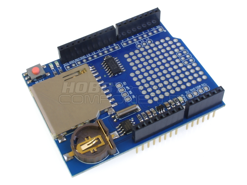

This data logger shield provides an Arduino Uno, Leonardo, or Mega with the ability to log sensor data to an SD card with the minimum of set-up. The shield provides sever useful features:
Real Time Clock Module
The shield includes the very popular DS1307 battery backed real time clock (RTC). This RTC will keep an accurate track of the data and time for up to several years, even when then shield isn't being powered.
SD Card reader
A standard SD card reader is provided to allow FAT16 or FAT32 formatted SD cards up to 32GB in size to be read or written to and is compatible with the standard SD card library. The shield also contains appropriate level shifting circuitry to protect the 3.3V interface of your SD card.
Prototyping area
A very useful protoyping area consisting of a grid of pads on a standard 0.1" pitch provide an area to add your own components such as sensors to interface to your Arduino board.
LED's L1 & L2
Two additional LEDs have been added which can be mapped to any of your Arduino's digital pins for use as visual indicators.
Standard Arduino headers.
The shield has a standard set of Arduino headers allowing additional compatible shields to be stacked.
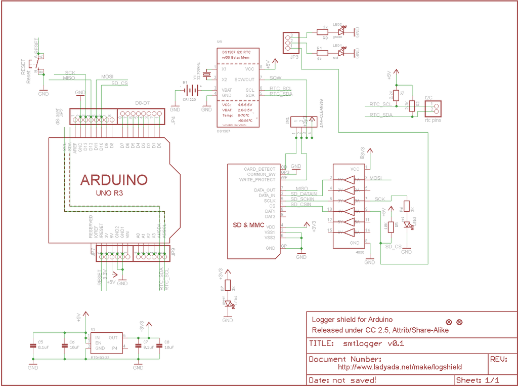
This product is manufactured by Deek-Robot and is derived from the Adafruit(TM) Data logger reference design which was released under the Creative commons Attribution-ShareAlike 3.0 licence http://creativecommons.org/licenses/by-sa/3.0/.
Order Yours Here.


Code: Select all
/* FILE:    Data_Logger_Shield_HCARDU0093_Example
   DATE:    24/02/15
   VERSION: 0.1

REVISIONS:

24/02/15 Created version 0.1

This is an example of how to use the Hobby Components data logger shield
(HCMODU0093). This shield contains a battery backed DS1307 real time clock
and an SD card interface. This allows any sensor data read by your Arduino
to be stored with an accurate time stamp to an SD card. In this example sketch
we will continually read the value of an LM35 temperature sensor and store the
result together with the current time and date to a CSV file. This file can then
be loaded into a spreadsheet such as Excel or Open Office.

To use this sketch you will require the HCTRC library which is available for
download in the software section of our support forum. You will also need to
connect an LM35 temperature sensor as follows:

LM35.....Arduino
Pin 1....+5V
Pin 2....Analogue pin A0
Pin 3....GND

You may copy, alter and reuse this code in any way you like, but please leave
reference to HobbyComponents.com in your comments if you redistribute this code.

This software may not be used directly for the purpose of promoting products that
directly compete with Hobby Components Ltd's own range of products.

THIS SOFTWARE IS PROVIDED "AS IS". HOBBY COMPONENTS MAKES NO WARRANTIES,
WHETHER EXPRESS, IMPLIED OR STATUTORY, INCLUDING, BUT NOT LIMITED TO, IMPLIED
WARRANTIES OF MERCHANTABILITY AND FITNESS FOR A PARTICULAR PURPOSE, ACCURACY OR
LACK OF NEGLIGENCE. HOBBY COMPONENTS SHALL NOT, IN ANY CIRCUMSTANCES, BE LIABLE
FOR ANY DAMAGES INCLUDING, BUT NOT LIMITED TO, SPECIAL, INCIDENTAL OR
CONSEQUENTIAL DAMAGES FOR ANY REASON WHATSOEVER. */


/* Include the wire library */
#include <Wire.h>
/* Include the Hobby Components RTC library */
#include <HCRTC.h>
/* Include the standard SD card library */
#include <SD.h>

/* The RTC has a fixed addresses of 0x68 */
#define I2CDS1307Add 0x68

/* DIO pin used to control the SD card CS pin */
#define SD_CS_DIO 10

/* Define the analogue pin used to read the temperature sensor (A0) */
#define LM35Pin 0

/* Create an instance of HCRTC library */
HCRTC HCRTC;

/* Create an instance of the standard SD card library */
File DataFile;

/* This will store the current temperature reading */
float Temperature;


void setup()
{
  /* Initialise the serial port */
  Serial.begin(9600);

  /* Set internal 2.56V reference for analogue pins */
  analogReference(INTERNAL);

  /* Set the SD card CS pin to an output */
  pinMode(SD_CS_DIO, OUTPUT);

  /* Use the RTCWrite library function to set the time and date.
     Parameters are: I2C address, year, month, date, hour, minute, second,
     day of week. You would normally only need to do this once */
  HCRTC.RTCWrite(I2CDS1307Add, 15, 2, 24, 14, 21, 0, 2);

  /* Initialise the SD card */
  if (!SD.begin(SD_CS_DIO))
  {
    /* If there was an error output this to the serial port and go no further */
    Serial.println("ERROR: SD card failed to initialise");
    while(1);
  }else
  {
    Serial.println("SD Card OK");
  }
}


/* Main Loop */
void loop()
{
  /* Read the LM35 connected to the analogue pin and convert to oC */
  Temperature = analogRead(LM35Pin) / 9.31;

  /* Read the current time from the RTC module */
  HCRTC.RTCRead(I2CDS1307Add);

  /* Lets output this data to the serial port */
  Serial.print(HCRTC.GetDateString());
  Serial.print(", ");
  Serial.print(HCRTC.GetTimeString());
  Serial.print(", ");
  Serial.println(Temperature);

  /* Open the data.csv file to save our data to.
     If the file already exists it will just tag our new data onto the end of it */
  DataFile = SD.open("data.csv", FILE_WRITE);

  if (DataFile)
  {
    DataFile.print(HCRTC.GetDateString());
    DataFile.print(", ");
    DataFile.print(HCRTC.GetTimeString());
    DataFile.print(", ");
    DataFile.println(Temperature);
    DataFile.close();
  }

  /* Wait a second before reading again */
  delay(1000);
}
To use the shield's RTC with the above example sketch please download the HCRTC library available from the software section of our support forum here:
http://forum.hobbycomponents.com/viewto ... =58&t=1357