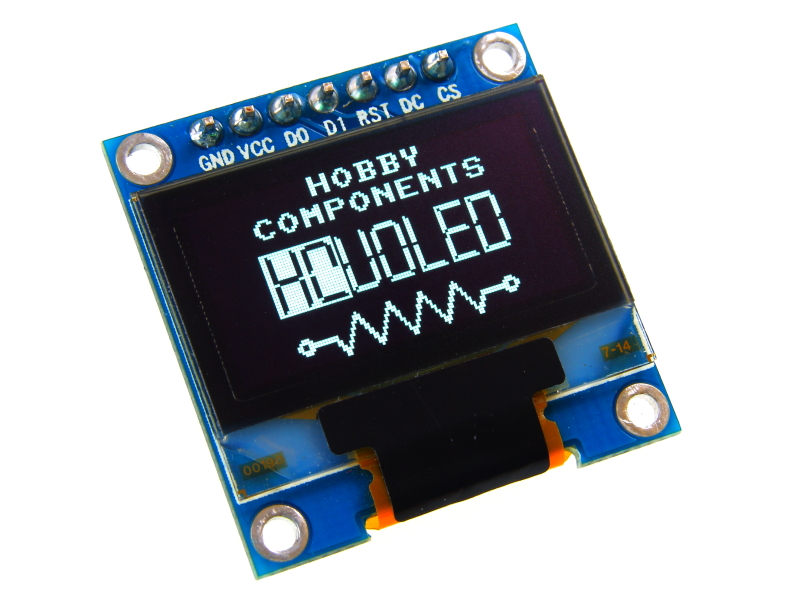

These tiny 0.96 inch uOLED displays have a resolution of 128 x 64 pixels and use a standard (SPI) serial interface for communication. Based on the SSD1306 controller, the module is available in both white and blue pixel colours. Pre-written libraries for Arduino are freely available including our own HCuOLED library for Arduino compatible development boards.

Module size: 27.3*27.8mm
High pixel density
Resolution: 128X64
Super wide viewing angle: more than 160°
Ultra-low power consumption: normal display 0.06W (far below the TFT display)
Wide supply range: DC 3V-5V (without any changes, directly compatible with common 3.3V and 5V power supply system)
Industrial grade: Operating temperature range -30 C ~ 70 C
Ultra-small size: (length) 27.8MM * (W) 27.3MM * (thickness) 4.3MM
Chip select CS signal allows for multiple SPI devices on the same bus.
Compatible tolerant interface.
OLED screen, internal drive chip: SSD1306
Pixel Colour: White (HCMODU0050), Blue (HCMODU0052)

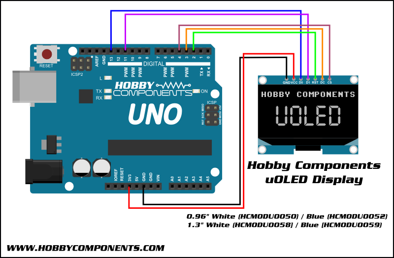
1....GND: Power ground
2....VCC: 3.3V or 5V power supply
3....D0 / SCK: CLK Clock
4....D1 / SDA: MOSI data
5....RST: Reset
6....DC: data / command
7....CS: Chip select signal
Dimensions:


Connecting multiple displays:
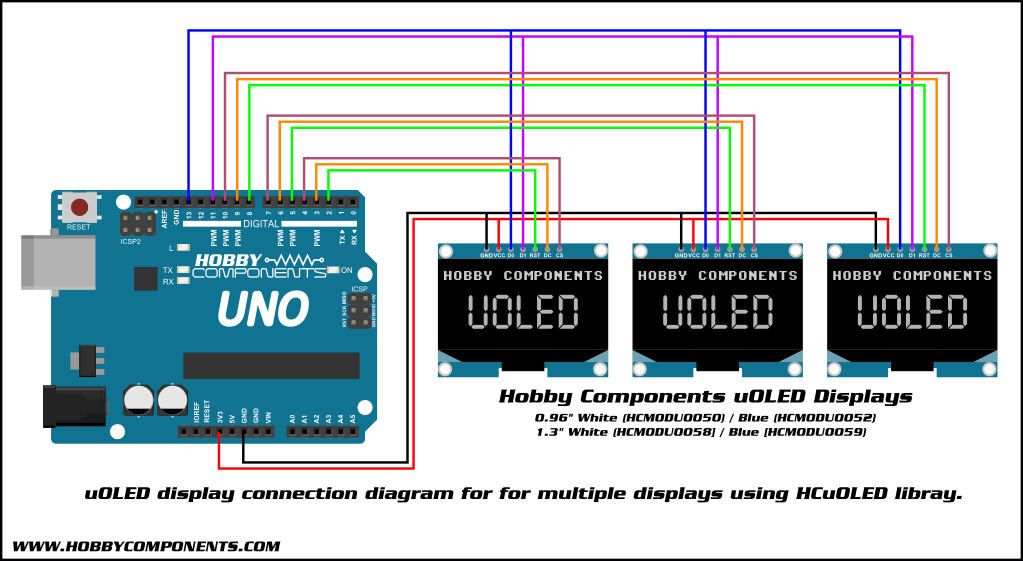
Note that when using the HCuOLED library, if you don't require the option of resetting multiple displays individually you can connect the reset pins on each module together and drive them from one digital pin on your Arduino. Therefore you will only require an additional 2 digital pins per display.

- #include "HCDisplay.h"
- // Default pins
- #define CS_PIN 4
- #define DC_PIN 3
- #define RST_PIN 2
- HCDisplay HCDisplay; //Creates an instance of the HCDisplay library
- unsigned int MaxX, MaxY;
- boolean FGColour = 1;
- void setup()
- {
- // Initialise the display
- HCDisplay.Init(CS_PIN, DC_PIN, RST_PIN); //Initialise the display
- /* Get the screens X & Y resolution */
- MaxX = HCDisplay.ResX() - 1;
- MaxY = HCDisplay.ResY() - 1;
- /* Draw a boarder */
- HCDisplay.Rect(0 , 0, MaxX, MaxY, OUTLINE, 1);
- HCDisplay.Rect(0 + 3 , 0 + 3, MaxX - 3, MaxY - 3, OUTLINE, 1);
- /* Print some text */
- HCDisplay.Pos(44,8);
- HCDisplay.Print("Hobby");
- HCDisplay.Pos(24,18);
- HCDisplay.Print("Components");
- HCDisplay.Pos(16,30);
- HCDisplay.Print("0.9\" I2C OLED");
- /* Change the font */
- HCDisplay.SetFont(MedProp_12ptFont);
- }
- void loop()
- {
- /* Make some text flash by swapping the texts foreground and background colours */
- HCDisplay.SetFG(FGColour);
- HCDisplay.SetBG(!FGColour);
- HCDisplay.Pos(10,42);
- HCDisplay.Print("HCMODU0150");
- FGColour = !FGColour;
- delay(200);
- }

HCDisplay Arduino library for above sketch is available for download from the software section of our support forum here:
viewtopic.php?f=58&t=2827
FAQ:
Does this module support I2C?
By default this module uses an SPI interface. The module can be modified to support I2C but this requires removal and linking surface mount components and pads. Which pads will require linking or unlinking will depend greatly on the version of display shipped but will normally be shown in screenprint on the rear of the display.
Connections to the display via I2C are as follows:
MICRO.......DISPLAY
GND.........GND
3.3V........VDD
SCK.........SCK
SDA.........SDA
DIO.........RES
The DC pin will set the I2C address where DC low = 0x3C & DC high = 0x3D.
The HCuOLED library does not support these displays in I2C mode but they are supported via the U8GLIB library. You will need to uncomment the following constructor:
U8GLIB_SSD1306_128X64 u8g(U8G_I2C_OPT_NO_ACK); // Display which does not send AC
Also note that at time of writing, the U8GLIB library does not support automatic resetting of the display so you will need to connect the modules RES (reset) pin to a spare DIO pin on your Arduino and manually reset the display by pulsing the pin low before the U8GLIB is initialised. Alternatively you can connect the RES pin to the reset pin of your Arduino so that the display is reset when your Arduino is reset.
**PLEASE NOTE** These modules are sold as SPI displays and as they require a hardware modification to work in I2C we do not support them in this configuration. We cannot replace displays that have been damaged due to improper modification. The information above is only given for customers that are comfortable making this modification. We provide no guarantees or warranty as to its accuracy.
How do I connect this display to my Arduino Mega?
The HCuOLED library makes use of the Arduinos hardware SPI interface. This is actually in a different place on a Mega and so you will need to connect the display to the following pins:
MODULE..............MEGA
GND....................GND
VCC.....................3.3V
D0 (CLK)..............D52
D1 (DATA)............D51
RST (RESET).........D8
DC......................D9
CS (SS)...............D10
If you are using one of the example sketches remember to change the appropriate pin definitions at the top of the sketch.
I want to use the display with an Ethernet shield but the display doesn't work properly. How can I make it work?
This is because both the Ethernet shield and HCuOLED library both use the Arduinos hardware SPI interface causing a pin conflict. This can simply be resolved by moving the default pin for the displays CS (chip select) from D10 to a free pin such as D7. If you are using one of the example sketches remember to change the appropriate pin definition at the top of the sketch.
Datasheet:
Libraries, example code, and diagrams are provided as an additional free service by Hobby Components and are not sold as part of this product. We do no provide any guarantees or warranties as to their accuracy or fitness for purpose.
Descriptions and diagrams on this page are copyright Hobby Components Ltd and may not be reproduced without permission.