Order yours here
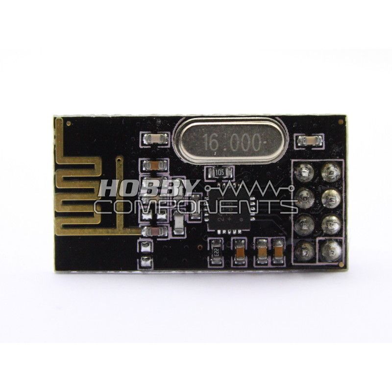
The nRF24L01 is a highly integrated, ultra low power (ULP) 2Mbps RF transceiver IC for the 2.4GHz ISM (Industrial, Scientific and Medical) band. With peak RX/TX currents lower than 14mA, a sub μA power down mode, advanced power management, and a 1.9 to 3.6V supply range, the nRF24L01 provides a true ULP solution enabling months to years of battery lifetime when running on coin cells or AA/AAA batteries. The Enhanced ShockBurst™ hardware protocol accelerator additionally offloads time critical protocol functions from the application microcontroller enabling the implementation of advanced and robust wireless connectivity with low cost 3rd-party microcontrollers.
The nRF24L01 module integrates a complete 2.4GHz RF transceiver, RF synthesizer, and baseband logic including the Enhanced ShockBurstâ„¢ hardware protocol accelerator supporting a high-speed SPI interface for the application controller allowing easy interface to microcontrollers and is ideal for low cost communication between Arduino compatible devices.
Worldwide 2.4GHz ISM band operation
• Up to 2Mbps on air data rate
• Ultra low power operation
• 11.3mA TX at 0dBm output power
• 12.3mA RX at 2Mbps air data rate
• 900nA in power down
• 22μA in standby-I
• On chip voltage regulator
• 1.9 to 3.6V supply range
• Enhanced ShockBurst™
• Automatic packet handling
• Auto packet transaction handling
• 6 data pipe MultiCeiver™
• 5V tolerant inputs
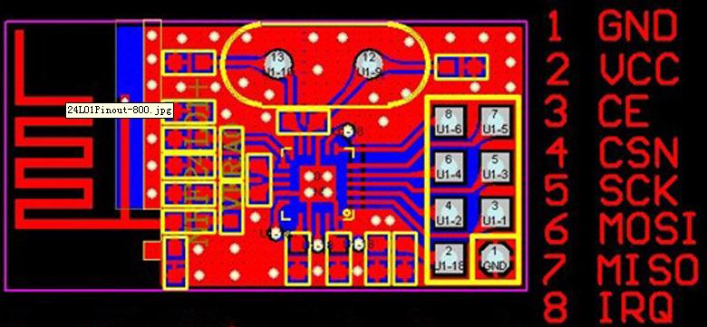
ARDUINO UNO AND MEGA CONNECTIONS
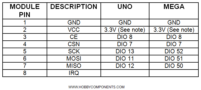
VCC of the module must be connected to a supply in the range of 1.9 to 3.6V. Connecting the module to the Arduino's 5V supply will damage it. The module has 5V tolerant DIO and therefore it is safe to directly interface it to an Arduino board’s 5V DIO. Please also be aware that in the past we have seen cases where the modules peak transmit power is in excess of what the 3.3V supply on an Arduino board is capable of supplying. We therefore suggest that when powering the module directly from an Arduino board that you attach a 10uF or greater capacitor across the modules VCC and GND pins.
Sensor Example
Code: Select all
/* FILE:    ARD_nRF24L01_Transceiver_Module_HCMODU0004_Sensor_Example.pde
*  DATE:    31/01/13
*  VERSION: 0.1
*
* This is an example of how to use the Hobby Components nRF24L01 2.4GHz wireless
* transceiver (HCMODU0004). This transceiver module is a very cost effective way
* to transmit data from one microcontroller to another over short distances. This
* simple example will configure the module using the freely available Mirf library
* to transmit the analogue value from analogue input A0 to a remote module.
*
*
* UNO/MEGA PINOUTS
*
* MODULE........UNO
* (1) GND.......GND
* (2) VCC.......3.3V (See note)
* (3) CE........DIO 8
* (4) CSN.......DIO 7
* (5) SCK.......DIO 13
* (6) MOSI......DIO 11
* (7) MISO......DIO 12
* (8) IRQ.......N/A

*
* MODULE........MEGA
* (1) GND.......GND
* (2) VCC.......3.3V (See note)
* (3) CE........DIO 8
* (4) CSN.......DIO 7
* (5) SCK.......DIO 52
* (6) MOSI......DIO 51
* (7) MISO......DIO 50
* (8) IRQ.......N/A
*
*
* VCC of the module must be connected to a supply in the range of 1.9 to 3.6V.
* Connecting the module to the Arduino's 5V supply will damage it. The module has
* 5V tolerant DIO and therefore it is safe to directly interface it to an Arduino
* board’s 5V DIO. Please also be aware that in the past we have seen cases where
* the modules peak transmit power is in excess of what the 3.3V supply on an
* Arduino board is capable of supplying. We therefore suggest that when powering
* the module directly from an Arduino board that you attach a 10uF or greater
* capacitor across the modules VCC and GND pins.
*
*
* You may copy, alter and reuse this code in any way you like, but please leave
* reference to HOBBYCOMPONENTS.COM in your comments if you redistribute this code.
*
* THIS SOFTWARE IS PROVIDED "AS IS". HOBBY COMPONENTS MAKES NO WARRANTIES, WHETHER
* EXPRESS, IMPLIED OR STATUTORY, INCLUDING, BUT NOT LIMITED TO, IMPLIED WARRANTIES OF
* MERCHANTABILITY AND FITNESS FOR A PARTICULAR PURPOSE, ACCURACY OR LACK OF NEGLIGENCE.
* HOBBY COMPONENTS SHALL NOT, IN ANY CIRCUMSTANCES, BE LIABLE FOR ANY DAMAGES,
* INCLUDING, BUT NOT LIMITED TO, SPECIAL, INCIDENTAL OR CONSEQUENTIAL DAMAGES FOR ANY
* REASON WHATSOEVER.
*
*/


/* Include the SPI anf Mirf libraries */
#include <SPI.h>
#include <Mirf.h>
#include <nRF24L01.h>
#include <MirfHardwareSpiDriver.h>

/* Current analogue input value */
unsigned int uiData;

void setup(){
  Serial.begin(9600);

  /* Define the DIO used to SPI CSN & CE. Defaults are DIO
  *  7 & 8 respectively. */
  Mirf.cePin = 8;
  Mirf.csnPin = 7;

  Mirf.spi = &MirfHardwareSpi;

  /* Initialise the module */
  Mirf.init();

  /* Set the receiving address of this module. This must be a 5 byte
  *  character string */
  Mirf.setRADDR((byte *)"SENS1");

  /* Set the payload length to size unsigned int (size of data from
  *  the analogue input A0) */
  Mirf.payload = sizeof(uiData);

  /* Set the channel. Channel 90 = 2.490GHz */
  Mirf.channel = 90;

  /* Configure the module */
  Mirf.config();

  Serial.println("Module initialised");
}


/******* Main Program ********/
void loop()
{
  /* Set transmit address to client module 1 */
  Mirf.setTADDR((byte *)"CLI01");

  /* Read the analogue input A0... */
  uiData = analogRead(A0);

  Serial.print("Sending: ");
  Serial.println(uiData);

  /* ...and send it to the client */
  Mirf.send((byte *)&uiData);

  /* Wait for module to finish sending */
  while(Mirf.isSending());

  /* Wait a little */
  delay(1000);
}
Client Example
Code: Select all
/* FILE:    ARD_nRF24L01_Transceiver_Module_HCMODU0004_Client_Example.pde
*  DATE:    31/01/13
*  VERSION: 0.1
*
* This is an example of how to use the Hobby Components nRF24L01 2.4GHz wireless
* transceiver (HCMODU0004). This transceiver module is a very cost effective way
* to transmit data from one microcontroller to another over short distances. This
* simple example will configure the module using the freely available Mirf library
* to receive the analogue value from analogue input A0 on a remote module.
*
*
* UNO/MEGA PINOUTS
*
* MODULE........UNO
* (1) GND.......GND
* (2) VCC.......3.3V (See note)
* (3) CE........DIO 8
* (4) CSN.......DIO 7
* (5) SCK.......DIO 13
* (6) MOSI......DIO 11
* (7) MISO......DIO 12
* (8) IRQ.......N/A

*
* MODULE........MEGA
* (1) GND.......GND
* (2) VCC.......3.3V (See note)
* (3) CE........DIO 8
* (4) CSN.......DIO 7
* (5) SCK.......DIO 52
* (6) MOSI......DIO 51
* (7) MISO......DIO 50
* (8) IRQ.......N/A
*
*
* VCC of the module must be connected to a supply in the range of 1.9 to 3.6V.
* Connecting the module to the Arduino's 5V supply will damage it. The module has
* 5V tolerant DIO and therefore it is safe to directly interface it to an Arduino
* board’s 5V DIO. Please also be aware that in the past we have seen cases where
* the modules peak transmit power is in excess of what the 3.3V supply on an
* Arduino board is capable of supplying. We therefore suggest that when powering
* the module directly from an Arduino board that you attach a 10uF or greater
* capacitor across the modules VCC and GND pins.
*
*
* You may copy, alter and reuse this code in any way you like, but please leave
* reference to HOBBYCOMPONENTS.COM in your comments if you redistribute this code.
*
* THIS SOFTWARE IS PROVIDED "AS IS". HOBBY COMPONENTS MAKES NO WARRANTIES, WHETHER
* EXPRESS, IMPLIED OR STATUTORY, INCLUDING, BUT NOT LIMITED TO, IMPLIED WARRANTIES OF
* MERCHANTABILITY AND FITNESS FOR A PARTICULAR PURPOSE, ACCURACY OR LACK OF NEGLIGENCE.
* HOBBY COMPONENTS SHALL NOT, IN ANY CIRCUMSTANCES, BE LIABLE FOR ANY DAMAGES,
* INCLUDING, BUT NOT LIMITED TO, SPECIAL, INCIDENTAL OR CONSEQUENTIAL DAMAGES FOR ANY
* REASON WHATSOEVER.
*
*/

/* Include the SPI anf Mirf libraries */
#include <SPI.h>
#include <Mirf.h>
#include <nRF24L01.h>
#include <MirfHardwareSpiDriver.h>

/* Holds the current received analogue value */
unsigned int uiData;


void setup(){
  Serial.begin(9600);

  /* Define the DIO used to SPI CSN & CE. Defaults are DIO
  *  7 & 8 respectively. */
  Mirf.cePin = 8;
  Mirf.csnPin = 7;

  Mirf.spi = &MirfHardwareSpi;

  /* Initialise the module */
  Mirf.init();

  /* Set the receiving address of this module. This must be a 5 byte
  *  character string */

  Mirf.setRADDR((byte *)"CLI01");

  /* Set the payload length to size unsigned int (size of data from
  *  the analogue input A0) */
  Mirf.payload = sizeof(uiData);

  /* Set the channel. Channel 90 = 2.490GHz */
  Mirf.channel = 90;

  /* Configure the module */
  Mirf.config();

  Serial.println("Listening...");
}


/******* Main Program ********/
void loop()
{

  /* If we are not currently sending an there is new data available
   * then get the new data and output it to the UART */
  if(!Mirf.isSending() && Mirf.dataReady()){

    /* Get the data from the receive buffer */
    Mirf.getData((byte *) &uiData);

    /* And output it to the UART */
    Serial.print("Got packet:  ");
    Serial.println(uiData);
  }
}
Snapshot of Mirf library used to test these modules: FAQ
I can communicate with the module but I am receiving very little or no data, do I have a faulty module?
Not necessarily. A common cause of this is due to the power supply. Although the nominal power requirements of these modules is quite low, when the module is actually transmitting, for split seconds, the peak power requirements can be significantly higher. If your power supply is not capable of supplying or reacting to this peak requirement, it can cause the supply to the module to dip. This then causes the module to momentarily be kicked off frequency resulting in data loss. We have notice in our tests that this can happen when powering the modules directly from an Arduino board. The solution is to add a 10uF capacitor across the supply pins of the module.
I am getting a poor range, is there anything I can do to improve it?
RF is a bit of a black art and there are many factors that can affect the range of a signal; especially with any device that operates in the widely used 2.4GHz part of the frequency spectrum.
First thing to check is possible interference from nearby RF devices. Things such as routers, Bluetooth devices, microwave ovens all operate in the same part of the spectrum and can interfere with the module even if they aren't on the same channel (referred to as adjacent and in-band interferers). For an example of this, copy a large file over your WiFi network and then turn on the Bluetooth on your phone and watch the transfer rate tank. To resolve this, try changing channels on your devices or the module so that they are as far a part as possible. Also avoid locating the module close to relatively high power devices such as router as even if they are not on the same channel the router can still saturate and cause harmonic interferers in the modules receiver chain. Similar to trying to hold a conversation with someone when someone else nearby is shouting.
Next thing to check is where you have the module located. It's an easy thing to forget but the module has an integrated antenna and any metal objects placed nearby can block or detune its antenna. Make sure that you don't have any metal around the antenna such as metal chassis, wires, or even other electronics such as LCD screens. Make sure the antenna on the end of the module is in open space.
The signal path is another thing to consider. Microwaves do not like to go through things such as walls. The signal you are receiving is more likely to have got to its destination by bouncing off walls and other objects. As the signal can also take several different paths (multi-path) this cause areas of high and low signal strength. Just moving the module a few centimetres can make a big difference.
Finally orientation of the module can effect range. Although we don't have radiation patterns for these modules, as a general rule, making sure that both antenna's are in the same orientation can have as much as a 15dB increase in received signal strength.
Datasheet: