

The Longreach environmental sensor is a LoRa-based wireless transmitter that can automatically report temperature, humidity, pressure, and light levels (ambient & white) from a remote location. Being LoRa based it is able to transmit its sensor reading over exceptionally long distances (>1 kilometer in free space) far beyond common WiFi and Bluetooth based sensors. No programming skills are required to use this module, simply connect power via its microUSB socket and the module will automatically start transmitting its sensor readings at set intervals.
Note: To receive the sensor reading you will need a compatible LongReach module. For example, to receive the sensor readings to a computer you can use a LongReach USB module (SKU: HCMODU0251), or to receive them to a microcontroller such as an Arduino you will need a LongReach mLink module (SKU: HCMODU0250). See below for examples.

Specification:
Product code: HCMODU0252
Supply Voltage: 5V via microUSB connector or solder pads
Supply current: 9.8mA (idle), 150mA (Tx)
Radio Type: LoRa RM95
Range: >1 kilometre in free air
Frequency: 905MHz
Re-transmit period: 10 to 2560 seconds (default 60s)
Re-transmit accuracy: 0.5% @25oC
Address range: 0 to 255
Temp sensor range: -40 to 85oC
Temp sensor resolution: 0.01oC
Hum sensor range: 0 to 100%RH
Hum sensor resolution: 0.024%RH
Pressure sensor range: 300 to 1100hPa / mBar
Pressure sensor resolution: 0.01hPa / mBar
Light sensor range: 0 to 35232lx
Light sensor resolution: 0.54lx
Sensor output:
By default, the module sends all sensor readings to any compatible LongReach receiver once every 60 seconds. This interval can be adjusted by the user (see setting the re-transmit time section below). A compatible LongReach receiver will receive the sensor readings in a readable ASCII format, as shown:
TMP=<temp>
Where <temp> is a temperature sensor reading to 2 decimal places in oC. Values can range from -40.00 to 80.00.
HUM=<hum>
Where <hum> is a humidity sensor reading to 2 decimal places in %RH. Values can range from 0.00 to 100.00.
PRS=<pres>
Where <pres> is a barometric pressure sensor reading to 2 decimal places in hPa/mBar. Values can range from 300.00 to 1100.00.
LXA=<amb>
Where <amb> is an ambient light sensor reading to 2 decimal places in lux. Values can range from 0.00 to 35232.00.
LXW=<wht>
Where <wht> is a white light sensor reading to 2 decimal places in lux. Values can range from 0.00 to 35232.00.

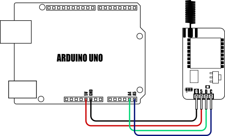
Receiving sensor readings with a microcontroller (Arduino):

To receive the sensor readings using an Arduino you will need a mLink Longreach module (SKU: HCMODU0250) connected to your Arduino and the mLink library installed.
- #include "mLink.h" // Include the mLink library
- mLink mLink; // Create an instance of the mLink class
- #define I2C_ADD 0x5F // Default I2C address for the mLink module
- char rxBuffer[32]; // Buffer to hold incoming message (up to 32 characters)
- // Variables to store the sensor values
- float temperature, humidity, pressure, lightAmbient, lightWhite;
- void setup()
- {
- Serial.begin(9600); // Start the serial monitor
- mLink.init(); // Initialize the mLink module
- // Enable LongReach mode
- mLink.LORA_LR_Mode(I2C_ADD, LR_MODE_ON);
- // Set to continuously receive data
- mLink.LORA_Mode(I2C_ADD, LORA_MODE_RXCONTINUOUS);
- Serial.println("Listening for sensor data...");
- }
- void loop()
- {
- // Check if data has been received
- if (mLink.LORA_Rx_Available(I2C_ADD))
- {
- // Get the number of bytes received
- byte size = mLink.LORA_Rx_Size(I2C_ADD);
- if (size > 32) size = 32;
- // Read the new data
- mLink.LORA_Rx_Read(I2C_ADD, size, rxBuffer);
- // Check which type of sensor data was received and print it out
- if(checkSensor("TMP=", rxBuffer))
- {
- temperature = getSensorVal(rxBuffer);
- Serial.print("Temperature = ");
- Serial.println(temperature);
- }
- else if(checkSensor("HUM=", rxBuffer))
- {
- humidity = getSensorVal(rxBuffer);
- Serial.print("Humidity = ");
- Serial.println(humidity);
- }
- else if(checkSensor("PRS=", rxBuffer))
- {
- pressure = getSensorVal(rxBuffer);
- Serial.print("Pressure = ");
- Serial.println(pressure);
- }
- else if(checkSensor("LXA=", rxBuffer))
- {
- lightAmbient = getSensorVal(rxBuffer);
- Serial.print("Ambient Light = ");
- Serial.println(lightAmbient);
- }
- else if(checkSensor("LXW=", rxBuffer))
- {
- lightWhite = getSensorVal(rxBuffer);
- Serial.print("White Light = ");
- Serial.println(lightWhite);
- Serial.println();
- }
- }
- }
- // Checks the first 4 characters of the received
- // message to see which sensor it is
- boolean checkSensor(char *sensor, byte *buffer)
- {
- return strncmp(buffer, sensor, 4) == 0;
- }
- // Converts the measurment part of the message
- // to a floating point number
- float getSensorVal(byte *buffer)
- {
- return atof(buffer + 4);
- }

mLink library: viewtopic.php?f=58&t=3001

Receiving sensor readings to a Raspberry Pi
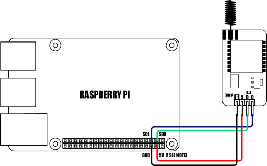
When connecting to a Raspberry Pi the mLink modules I2C pullup resistors should be removed. See the 'Removing the modules I2C pullup resistors' section below for more information.
- from mLink import mLink # Import the mLink module
- import time
- ml = mLink.mLink(1) # Create an instance of the module
- I2C_ADD = 0x5F # Default I2C address is 0x5F
- ml.LORA_LR_Mode(I2C_ADD, ml.LR_MODE_ON) # Put the module into LongReach mode
- ml.LORA_Mode(I2C_ADD, ml.LORA_MODE_RXCONTINUOUS) # Put module into continuous receive mode
- while 1:
- avail = ml.LORA_Rx_Available(I2C_ADD) # Check for new data
- if avail:
- size = ml.LORA_Rx_Size(I2C_ADD) # Get the size in bytes of the new data
- message = ml.LORA_Rx_Read(I2C_ADD, size) # Read out the message
- sMessage = ''.join(map(chr, message)) # Convert message from list to string
- # If message starts with "TMP=" it's a temperature measurement
- if sMessage[:4] == "TMP=":
- temperature = float(sMessage[4:])
- print("Temperature = ", temperature)
- # If message starts with "HUM=" it's a humidity measurement
- elif sMessage[:4] == "HUM=":
- humidity = float(sMessage[4:])
- print("Humidity = ", humidity)
- # If message starts with "PRS=" it's a pressure measurement
- elif sMessage[:4] == "PRS=":
- pressure = float(sMessage[4:])
- print("Pressure = ", pressure)
- # If message starts with "LXA=" it's an ambient light measurement
- elif sMessage[:4] == "LXA=":
- ambientLight = float(sMessage[4:])
- print("Ambient Light = ", ambientLight)
- # If message starts with "LXW=" it's a white light measurement
- elif sMessage[:4] == "LXW=":
- whitetLight = float(sMessage[4:])
- print("White Light = ", whitetLight, "\n")
- time.sleep(0.1)


To run this example, you’ll need a LongReach USB module connected to your PC to receive sensor readings. You’ll also need a serial terminal program to view the data. In this example, we’re using YAT (Yet Another Terminal).
Step 1: Connect to the Module
Open your terminal program and connect to the USB module’s serial port using a baud rate of 9600.
Step 2: Enable LongReach Mode
Type the following AT command into the terminal to enable LongReach mode:
AT+LRM=ON
Note: The command must be terminated with a Line Feed (LF) and Carriage Return (CR). Some terminal programs handle this automatically, depending on their settings. Make sure your terminal is configured correctly.
If the command is accepted, the module will reply with:
OK
Step 3: View Sensor Readings
Once the module is in LongReach mode, the terminal program will begin displaying any received sensor readings automatically.


Dimensions:

Setting the re-transmit time:
By default the module will transmit the sensor readings once every minute. This time can be set by the user from 10 seconds to 2560 seconds in 10 second increments. To change the re-transmit time perform the following steps:
Step 1)
Download the following PDF file containing a lookup table of switch settings. Use this table to find the switch settings for your required re-transmit time.
https://hobbycomponents.com/images/foru ... Lookup.pdf
Step 2)
With power removed from the module, set the module's 8 dip switches to match the ones shown in the lookup table.
Step 3)

Use a wire or paperclip to link the GND & T-A pads together as shown above.
Step 4)
With the pads still linked, connect power to the module.
Step 5)
Remove power from the module and set the dip switched back to their original state, or wherever address you require.
The module will now transmit sensor readings with the new re-transmit interval. The new interval will be stored in the modules non-volatile memory so only needs to be done once.
Disclaimer:
As with all wireless devices, external factors such as range and interference may cause transmissions to be corrupted or blocked. Therefore these devices should not be used in applications where control or monitoring is a critical requirement.
Libraries, example code, and diagrams are provided as an additional free service by Hobby Components and are not sold as part of this product. We do not provide any guarantees or warranties as to their accuracy or fitness for purpose.