LongReach (LoRa) mLink Module (HCMODU0250)

mLink serial I2C modules
Post Reply
admin
Site Admin
Posts: 879
Joined: Sun Aug 05, 2012 4:02 pm

LongReach (LoRa) mLink Module (HCMODU0250)

Post by admin » Fri Sep 06, 2024 9:41 am

Image

Image

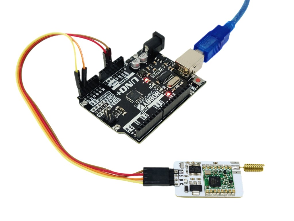
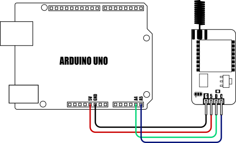
The LongReach mLink module is a LoRa-based wireless device that connects to most microcontrollers using a serial mLink (I2C) interface. Once connected, it enables your microcontroller to communicate with other devices through its built-in RM95 LoRa radio transceiver. By using two or more modules, you can establish wireless communication between multiple microcontrollers over far greater distances than technologies like WiFi or Bluetooth.
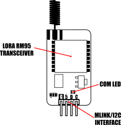
Please note: RM95 modules are a higher frequency variant of the RM96. As such they are fitted with an IC marked RM96 which operates at the higher 868MHz frequency band.


Image


The module is also compatible with other LongReach modules such as the LongReach USB module for communication from a microcontroller to a computer, or remote sensing and control using the LongReach 4CH Relay module or Tx module, etc.


Image


mLink I2C interface
As the module incorporates the mLink I2C interface it is also compatible with our range of mLink modules meaning it can be daisy-chained with other mLink modules such as LCD displays, keypads, sensors, relays etc., all via a single I2C interface and only requiring one compact library to be installed.

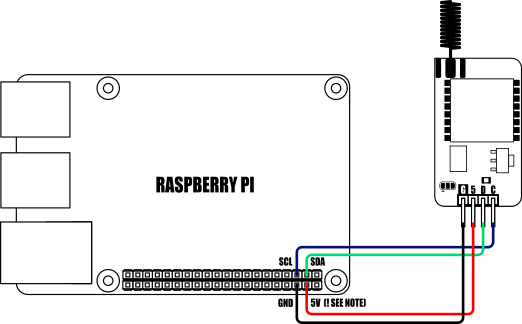
For Arduino and Raspberry Pi users we have a dedicated library and Python module which makes transmitting data and sensor readings via your sketches or python scripts as simple as possible (see below for examples and library links).


Specification:
Product code:				HCMODU0250
Supply voltage:				5V via mLink interface
Supply current:				2mA (sleep), 19mA (Rx), 150mA (Tx)
Radio type:				LoRa RM95
Range:					>1 kilometre in free air
Frequency:				868 to 915MHz
Max packet size:			256 bytes
Max bitrate (nominal):		9380bps (at -118dBm sensitivity)
Interface:					4 pin male mLink 0.1” headerI2C 
Interface speed:			400kbits/s (fast mode)
I2C default address (HEX):		0h5F
Maximum number of modules:	5 with pullups fitted, 112 with pullups removed**
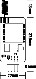
Dimensions (ex antenna):		42mm x 22mm x 5mm


*Note the maximum number of connected modules will depend on cable lengths and power requirements of each module. Do not exceed 5 mLink modules connected in series with I2C pullups fitted to all modules. For disconnecting pullups see forum post.


Image


Image


Send example

Send some example text:

This sketch uses the mLink library to send some example text to a remote module.

  1. #include "mLink.h"                                    // Include the library
  2.  
  3.  
  4. mLink mLink;                                          // Create an instance of the library
  5.  
  6.  
  7. #define I2C_ADD 0x5F                                  // Default I2C address
  8.  
  9.  
  10. char data[] = "Hello!";                               // Some example data to send
  11.  
  12.  
  13. void setup()
  14. {
  15.   mLink.init();                                       // Initialise the library
  16. }
  17.  
  18.  
  19.  
  20. void loop()
  21. {
  22.   mLink.LORA_Tx_Load(I2C_ADD, sizeof(data), data);    // Load the data into the Tx buffer
  23.  
  24.  
  25.   mLink.LORA_Tx_Send(I2C_ADD);                        // Send it
  26.  
  27.  
  28.   while(!mLink.LORA_Tx_Done(I2C_ADD));                // Wait for module to finish transmitting
  29.  
  30.  
  31.   delay(2000);                                        // Wait a little before sending again
  32. }

Receive example

Receive some data example:

This sketch uses the mLink library to display a value representing the Arduino 'up time'
  1. #include "mLink.h"                                    // Include the library
  2.  
  3.  
  4. mLink mLink;                                          // Create an instance of the library
  5.  
  6.  
  7. #define I2C_ADD 0x5F                                  // Default I2C address
  8.  
  9.  
  10. byte rxBuffer[255];                                   // Buffer to hold Rx data (max 255 bytes)
  11.  
  12.  
  13.  
  14. void setup()
  15. {
  16.   Serial.begin(9600);
  17.  
  18.   mLink.init();                                       // Initialise the library
  19.  
  20.  
  21.   mLink.LORA_Mode(I2C_ADD, LORA_MODE_RXCONTINUOUS);   // Put the module into continuous receive mode
  22. }
  23.  
  24.  
  25.  
  26. void loop()
  27. {
  28.   byte avail = mLink.LORA_Rx_Available(I2C_ADD);      // Check for new data
  29.  
  30.  
  31.   if(avail == 1)                                          
  32.   {
  33.     byte size = mLink.LORA_Rx_Size(I2C_ADD);          // Get the length of the data in bytes
  34.  
  35.  
  36.     mLink.LORA_Rx_Read(I2C_ADD, size, rxBuffer);      // Read the data into the buffer
  37.  
  38.  
  39.     int rssi = mLink.LORA_RSSI(I2C_ADD);              // Get the signal strength (RSSI)
  40.  
  41.  
  42.     Serial.print("Size = "); Serial.println(size);    // Print out the details
  43.     Serial.print("RSSI = "); Serial.println(rssi);
  44.  
  45.  
  46.     Serial.print("Data = ");                          // Print out the data in hex
  47.     for(byte i = 0; i < size; i++)
  48.     {
  49.       Serial.print(rxBuffer[i], HEX);
  50.       Serial.print(":");
  51.     }
  52.  
  53.  
  54.     Serial.println(); Serial.println();
  55.   }
  56. }


Image


Image

Send example

mLink LoRa transmit data example:

This example demonstrates how to transmit raw data to a remote module
Use this script in conjunction with the mLink LoRa receive example.

To use this script you will need to have the mLink module installed.
Please see library forum thread for more information

  1. from mLink import mLink                             # Import the mLink module
  2. import time
  3.  
  4. ml = mLink.mLink(1)                                 # Create an instance of the module
  5.  
  6. I2C_ADD = 0x5F                                      # Default I2C address is 0x5F
  7.  
  8.  
  9. data = ['H','E','L','L','O','!']                    # Create a list of data to send
  10.  
  11.  
  12. while 1:
  13.     ml.LORA_Tx_Load(I2C_ADD, data, len(data))       # Load the Tx buffer
  14.  
  15.     ml.LORA_Tx_Send(I2C_ADD, 0)                     # Send the data
  16.  
  17.     while not(ml.Tx_Done(I2C_ADD)):                 # Wait for data to be transmitted
  18.         continue
  19.  
  20.     time.sleep(10)                                  # Wait a little before sending again

Receive example

mLink LoRa receive data example:

This example demonstrates how to receive raw data from a remote module.
Use this script in conjunction with the mLink LoRa transmit example.

To use this script you will need to have the mLink module installed.
Please see library forum thread for more information

  1. from mLink import mLink                             # Import the mLink module
  2. import time
  3.  
  4. ml = mLink.mLink(1)                                 # Create an instance of the module
  5.  
  6. I2C_ADD = 0x5F                                      # Default I2C address is 0x5F
  7.  
  8.  
  9. ml.LORA_Mode(I2C_ADD, ml.LORA_MODE_RXCONTINUOUS)    # Put module into continuous receive mode
  10.  
  11.  
  12. while 1:
  13.     avail = ml.LORA_Rx_Available(I2C_ADD)           # Check for new data
  14.    
  15.     if avail:
  16.         size = ml.LORA_Rx_Size(I2C_ADD)             # Get the size in bytes of the new data
  17.         rssi = ml.LORA_RSSI(I2C_ADD)
  18.         data = ml.LORA_Rx_Read(I2C_ADD, size)       # Read out the data
  19.         print("Size = ", size)                      # Print out the size in bytes
  20.         print("RSSI = ", rssi)                      # Print out the size in bytes
  21.         print(data)                                 # Print out the raw data
  22.         print(''.join(map(chr, data)))              # Print out the data as an ASCII string
  23.        
  24.     time.sleep(1)
  25.  

LongReach send example

mLink LongReach transmit data example:

This example demonstrates how to transmit a command to a LongReach
module. The script will turn relay 0 on a LongReach relay module
(see SKU: HCMODU0249) on and off every 2 seconds suing the SW0=x
command.

If you have 2 mLink modules you can also use this script in
conjunction with the mLink LongReach receive example to send LongReach
commands from one Pi to another.

To use this script you will need to have the mLink module installed.
Please see library forum thread for more information

  1. from mLink import mLink                             # Import the mLink module
  2. import time
  3.  
  4. ml = mLink.mLink(1)                                 # Create an instance of the module
  5.  
  6. I2C_ADD = 0x5F                                      # Default I2C address is 0x5F
  7.  
  8. relay0_On = "SW0=1"                                 # Relay 0 ON command
  9. relay0_Off = "SW0=0"                                # Relay 0 OFF command
  10. LR_Dest_Add = 0                                     # Dest LongReach device address
  11.  
  12. ml.LORA_LR_Mode(I2C_ADD, ml.LR_MODE_ON)             # Put the module into LongReach mode
  13.  
  14.  
  15. while 1:
  16.     ml.LORA_Tx_Load(I2C_ADD, 5, relay0_On)          # Load the Tx buffer with the relay on command
  17.     ml.LORA_Tx_LR_Send(I2C_ADD, LR_Dest_Add)        # Send the command
  18.     time.sleep(2)  
  19.    
  20.     ml.LORA_Tx_Load(I2C_ADD, 5, relay0_Off)         # Load the Tx buffer with the relay off command
  21.     ml.LORA_Tx_LR_Send(I2C_ADD, LR_Dest_Add)        # Send the command
  22.     time.sleep(2)

LongReach receive example

mLink LongReach receive data example:

This example demonstrates how to receive a command from a LongReach
module (e.g. digital Tx module SKU: HCMODU0248).

If you have 2 mLink modules you can also use this script in
conjunction with the mLink LongReach send example to send LongReach
commands from one Pi to another.

To use this script you will need to have the mLink module installed.
Please see library forum thread for more information:

  1. from mLink import mLink                             # Import the mLink module
  2. import time
  3.  
  4. ml = mLink.mLink(1)                                 # Create an instance of the module
  5.  
  6. I2C_ADD = 0x5F                                      # Default I2C address is 0x5F
  7.  
  8.  
  9.  
  10. ml.LORA_LR_Mode(I2C_ADD, ml.LR_MODE_ON)             # Put the module into LongReach mode
  11. ml.LORA_Mode(I2C_ADD, ml.LORA_MODE_RXCONTINUOUS)    # Put module into continuous receive mode
  12.  
  13.  
  14. while 1:
  15.     avail = ml.LORA_Rx_Available(I2C_ADD)           # Check for new data
  16.    
  17.     if avail:
  18.         size = ml.LORA_Rx_Size(I2C_ADD)             # Get the size in bytes of the new data
  19.         rssi = ml.LORA_RSSI(I2C_ADD)                # Get the RSSI level
  20.         add = ml.LORA_Rx_Address(I2C_ADD)           # Get the LongReach destination address
  21.         data = ml.LORA_Rx_Read(I2C_ADD, size)       # Read out the command
  22.  
  23.         print("Address=", add)                      # Print out the address
  24.         print("Size=", size)                        # Print out the size in bytes
  25.         print("RSSI=", rssi)                        # Print out the RSSI level
  26.         print("Raw data=", data)                    # Print out the command as raw data
  27.         print("Command=", ''.join(map(chr, data)))  # Print out the command as ASCII
  28.        
  29.     time.sleep(1)


Image


Dimensions:


Image


Removing I2C pullups:


Image

If your development board already has pullups for its I2C interface fitted, or you wish to connect more than 5 mLink boards to the same I2C interface, then you can remove the pullups for the additional boards by cutting the tracks between the solder pads shown below.


Image


mLink Arduino library

viewtopic.php?f=58&t=3001

Please note that you will need at least V2.2.0 (09 Sep 2024) of the library to support this module. If you have an older version already installed please update it to the latest version.


mLink Raspberry Pi Python module
The mLink python module can be installed with the following terminal command:

  1. pip install hc-mlink

Alternatively the library can be manually installed by downloading it from the forum and unzipping it to your project folder. See the Python module forum thread for more information and download link:
viewtopic.php?f=131&t=3062&p=8592#p8592

Please note that in some cases there may be additional configuration required. If you have issues getting your Raspberry Pi to communicate with the mLink module then please see the Python module forum thread here: viewtopic.php?f=131&t=3062


mLink Specifications and Register Map

https://hobbycomponents.com/downloads/m ... V1_0_1.pdf


FAQ:

When I use my terminal program to enter an AT command the module just responds with ‘Error’

This could be caused by one of two things:

All AT commands must be terminated with a carriage return and a linefeed (CR+LF). You will need to set this in your terminal program.

By default a complete AT command including the CR+LF must be entered within ~2 seconds. If you are typing the command in manually and sending each character of the command one at a time then this may be the cause of the issue.

Either use a terminal program that can send the command in one go or try cutting and pasting the command into the terminal program.

You can change the default timeout time by using the AT+ATT command.


When I connect power to the module the LED does not illuminate, is it faulty?

The LED is a communication LED and will blink whenever there is communication between the USB interface or the RF interface. When there is no communication the LED will default to being off.


Libraries, example code, and diagrams are provided as an additional free service by Hobby Components and are not sold as part of this product. We do not provide any guarantees or warranties as to their accuracy or fitness for purpose.

Post Reply

Return to “mLink”