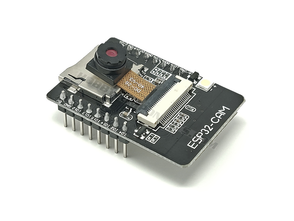

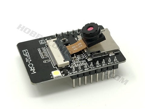
The ESP32-CAM is a WIFI + Bluetooth dual-mode development board based on the ESP32 microcontroller. It can be used as a standard ESP32 development board but also includes two additional features of an SVGA camera LED flash, and TF card socket.
The ESP32-CAM is fully supported by the Arduino IDE via the boards manager feature and includes examples (see below for setup and webcam example).
PLEASE NOTE THAT TO PROGRAM THIS BOARD YOU WILL NEED A SUITABLE USB TO SERIAL ADAPTER. Unless you have experience in programming ESP32s with USB adapters we strongly recommend purchasing the optional USB adapter board as this is by far the simplest way to program the ESP32-CAM:
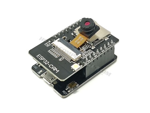
Image shows ESP32-CAM with programming adapter board (sold separately)
Features:
ESP integrates WiFi, traditional Bluetooth and BLE Beacon, with 2 high-performance 32-bit LX6 CPUs, 7-stage pipeline architecture, main frequency adjustment range 80MHz to 240MHz, on-chip sensor, Hall sensor, temperature sensor, etc. Fully compliant with WiFi 802.11b/g/n/e/i and Bluetooth 4.2 standards, it can be used as a master mode to build an independent network controller, or as a slave to other host MCUs to add networking capabilities to existing devices.
ESP32-CAM can be widely used in various IoT applications. It is suitable for home smart devices, industrial wireless control, wireless monitoring, QR wireless identification, wireless positioning system signals and other IoT applications. It is an ideal solution for IoT applications
- Ultra-small 802.11b/g/n Wi-Fi + BT/BLE SoC module
- Low-power dual-core 32-bit CPU for application processors
- Up to 240MHz, up to 600 DMIPS
- Built-in 520 KB SRAM, external 4M PSRAM
- Supports interfaces such as UART/SPI/I2C/PWM/ADC/DAC
- Support OV2640 and OV7670 cameras with built-in flash (camera included)
- Support for images WiFI upload
- Support TF card
- Support multiple sleep modes
- Embedded Lwip and FreeRTOS
- Support STA/AP/STA+AP working mode
- Support Smart Config/AirKiss One-click distribution network
- Support for serial local upgrade and remote firmware upgrade (FOTA)
- Support secondary development
Package includes:
1 x ESP32-CAM Module
1 x Camera Module OV2640 2MP
Product Specifications:
Product code: 					HCDVBD0042
Module model: 					ESP32-CAM
Package: 						DIP-16
Size: 						27*40.5*4.5(±0.2)mm
SPI Flash: 						default 32Mbit
RAM: 						internal 520KB+external 4M PSRAM
Bluetooth: 					Bluetooth 4.2BR/EDR and BLE standards
Wi-Fi: 						802.11 b/g/n/e/i
Interfaces: 					UART, SPI, I2C, PWM TF card
Maximum support: 				4G
IO ports: 						9
Serial port rate: 				default 115200 bps
Image output format: 			JPEG (only supported by OV2640), BMP, GRAYSCALE
Spectrum range: 				2412 ~ 2484MHz
Antenna form: 					onboard PCB antenna , gain 2dBi
Transmit power: 				802.11b: 17±2 dBm (@11Mbps)
802.11g: 						14±2 dBm (@54Mbps)
802.11n: 						13±2 dBm (@MCS7)
Receiving sensitivity: 			CCK, 1 Mbps : -90dBm
CCK, 11 Mbps: 					-85dBm
6 Mbps (1/2 BPSK): 				-88dBm
54 Mbps (3/4 64-QAM): 			-70dBm
MCS7 (65 Mbps, 72.2 Mbps): 		-67dBm
Power consumption: 				Turn off the flash: 180mA@5V
Flash on (brightness maximum):	 310mA@5V
Deep-sleep: 					The lowest power consumption can reach 6mA@5V
Modem-sleep: 					up to 20mA@5V
Light-sleep: 					up to 6.7mA@5V
Security: 						WPA/WPA2/WPA2-Enterprise/WPS
Power supply range: 				5V
Operating temperature: 			-20 °C ~ 85 °C
Storage environment: 			-40 °C ~ 90 °C, < 90%RH
Adding board support to the Arduino IDE:
Latest versions of the Arduino IDE allow for adding additional 3rd party board support directly from within the Arduino IDE. To add support for the this board simply open up your Arduino IDE and follow these steps:
1) Go to File->Preferences
2) In the window that opens up, find the text box labelled 'Additional Boards Manager URLs:' and paste the following line into it…
https://raw.githubusercontent.com/espre ... index.json
...then click the OK button to close the window.
3) Next go to Tools->Board->Boards Manager
4) In the window that opens up, look for the entry titled 'esp32' (hint: you can type esp32 into the filter box at the top of the window to find it) and click on it.
5) In the bottom right-hand corner of this entry you should now see an install button appear. Click on this and board manager will then automatically add all the files necessary to support the ESP32. This may take a few minutes depending on the speed of your internet connection.
6) Now under Tools->Board->ESP32 Arduino you will see a set of new additional esp32 based board types including one labelled 'AI Thinker ESP32-CAM'.
7) Select it as the board type and now under the Tools menu you should see new options for this board. Leave them as the default but set the COM port to match the one for your board just like you would with any other Arduino.
You should now be able to flash a sketch to the board in the normal way.
Connecting the camera to the ESP32:
IMPORTANT: When inserting the camera to the module do not use excessive force during any part of the process. Doing so may damage the connector or ribbon cable. We cannot replace items damaged due to excessive force.
Step 1) Locate the black and white/cream camera socket on the ESP32 board.
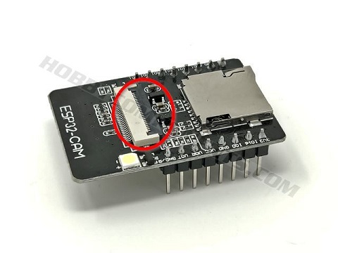
Step 2) To open the socket, using your fingernail, gently lift the outside edge of the black part of the connector upwards.
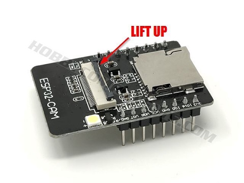
Step 3) Take the camera and with the lens pointing away from the ESP32 board gently but firmly push the end of the ribbon cable into the socket. The exposed connector parts of the cable should snuggly fit all the way into the connector (see image).
If you’re having trouble getting the cable to fit into the socket, try wiggling the cable very slightly whilst firmly pushing it into the socket.
Step 4) When you are sure that the cable is fully inserted, close the black part of the connector over the cable. It should firmly clip in place .
WEBCAM Example:
Please note: this example assumes that you have already connected your board to a USB serial programming adapter or the optional ESP-CAM adapter board. This example will also require connection to a WiFi router and a web browser.
Once you have followed the above Arduino setup and camera instructions you can test the module and camera by trying the example webcam sketch.
With the Arduino IDE open and ‘'AI Thinker ESP32-CAM’ selected as the board type, go to File->Examples->ESP32->Camera->CameraWebServer
The camera web server sketch should now open up, but before it can be uploaded to your board there are a couple of settings that need to be made:
First locate the camera selection section and make sure that all the camera options are commented out with a ‘//’ at the beginning of the line except the one for the CAMERA_MODEL_AI_THINKER camera like this:
- // ===================
- // Select camera model
- // ===================
- //#define CAMERA_MODEL_WROVER_KIT // Has PSRAM
- //#define CAMERA_MODEL_ESP_EYE // Has PSRAM
- //#define CAMERA_MODEL_ESP32S3_EYE // Has PSRAM
- //#define CAMERA_MODEL_M5STACK_PSRAM // Has PSRAM
- //#define CAMERA_MODEL_M5STACK_V2_PSRAM // M5Camera version B Has PSRAM
- //#define CAMERA_MODEL_M5STACK_WIDE // Has PSRAM
- //#define CAMERA_MODEL_M5STACK_ESP32CAM // No PSRAM
- //#define CAMERA_MODEL_M5STACK_UNITCAM // No PSRAM
- #define CAMERA_MODEL_AI_THINKER // Has PSRAM
- //#define CAMERA_MODEL_TTGO_T_JOURNAL // No PSRAM
- // ** Espressif Internal Boards **
- //#define CAMERA_MODEL_ESP32_CAM_BOARD
- //#define CAMERA_MODEL_ESP32S2_CAM_BOARD
- //#define CAMERA_MODEL_ESP32S3_CAM_LCD
Next, to connect to your router you will need to tell the sketch your router's SSID and WiFi password. Locate the following lines in the sketch….
- const char* ssid = "**********";
- const char* password = "**********";
…and replace the asterisks with your router's SSID and password like this:
- const char* ssid = "myRoutersSSID";
- const char* password = "myRoutersPAssword";
With these settings made you can now upload the sketch to your board.
Once uploaded, open up the Arduino monitor window by going to tools->serial monitor. In the monitor window that opens up make sure that in the bottom right and corner the BAUD rate is set to ‘115200 BAUD’.
If all goes well and the ESP32 is able to connect to your router you see various information reported in the monitor window with the last couple of lines reporting the modules IP address:
WiFi connected
Camera Ready! Use 'http://xxx.xxx.xxx.xxx' to connect
If you don’t see anything reported try resetting the module.
Copy the IP address reported in the previous step into your browser and when you hit enter you should see a webpage open containing various camera settings. To view the camera stream, press the ‘Start Stream’ button at the bottom of the page.
DOWNLOADS:
Schematic:
FAQ:
When I try to run a sketch it keeps reporting a brownout warning and then rebooting.
When WiFi, camera, and flash is enabled the module can use a lot of power. A brownout is usually and indication of either an insufficient power supply or USB cable. If you get this issue first try another USB cable.
Libraries, example code, and diagrams are provided as an additional free service by Hobby Components and are not sold as part of this product. We do not provide any guarantees or warranties as to their accuracy or fitness for purpose.
Descriptions and diagrams on this page are copyright Hobby Components Ltd and may not be reproduced without permission.