mLink Home Sensor (HCMODU0198)

mLink serial I2C modules
Post Reply
admin
Site Admin
Posts: 866
Joined: Sun Aug 05, 2012 4:02 pm

mLink Home Sensor (HCMODU0198)

Post by admin » Thu Feb 09, 2023 4:29 pm

Image


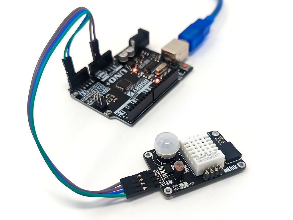
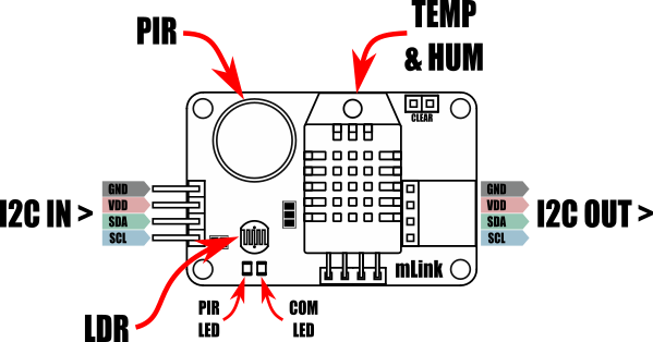
The mLink Home sensor is a compact multiple sensor module featuring a DHT22 temperature/humidity sensor, a LDR light sensor and a PIR motion detector. These features make this module ideal for sensing occupancy and environmental conditions within a room.

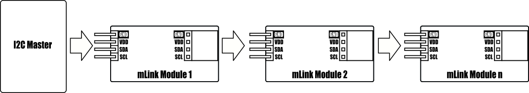
Communication with the sensors is made via the modules serial (I2C) interface which is compatible with microcontrollers featuring an I2C interface including most types of Arduinos. Being an mLink module it is also compatible with other modules in our mLink range and can simply be daisy-chained together allowing multiple different mLink modules to be controlled via one serial interface.


For Arduino users you can use the mLink library (see below for library and examples) to control any type of mLink module. Only one single instance of the library is needed to control multiple types of mLink modules resulting in very little resource overhead and therefore making it great for Arduinos with small amounts of memory and pin counts.

For Raspberry Pi users we have a Python module which can be installed via pip or downloaded and installed directly from our forum. Please see the mLink Python forum thread for requirements and download link here: viewtopic.php?f=131&t=3062&p=8592#p8592


Image


Image

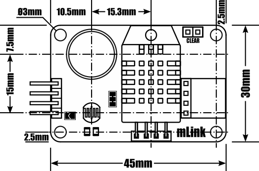
Module code:						HCMODU0198
Supply Voltage(VDD):					5V (3.3V with solder pad bridged - see forum post)
Current consumption:				7mA
Current consumption (sleep):			0.5mA
I2C Interface speed:					400kbits/s (fast mode)
I2C default address (HEX):				0h5B
Maximum number of modules:			5 with pullups fitted, 112 with pullups removed*
Temperature sensor range:			-40 to 80oC
Temperature sensor resolution:			0.1oC
Humidity sensor range:				0 to 10 %RH
Humidity sensor resolution:			0.1 %RH
LDR sensor range:					0 to 255
PIR Trigger on time:					~4 seconds
PIR Sensor angle:					100 degree cone
Sensor range:						~3 to 5 metres
Module dimensions ex headers (LxWxH):	45mm x 30mm x  18mm


*Note the maximum number of connected modules will depend on cable lengths and power requirements of each module. Do not exceed 5 mLink modules connected in series with I2C pullups fitted to all modules. For disconnecting pullups see forum post.


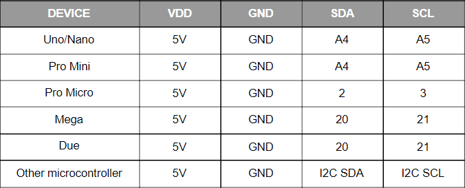
Arduino Connection Example:

Image


Image


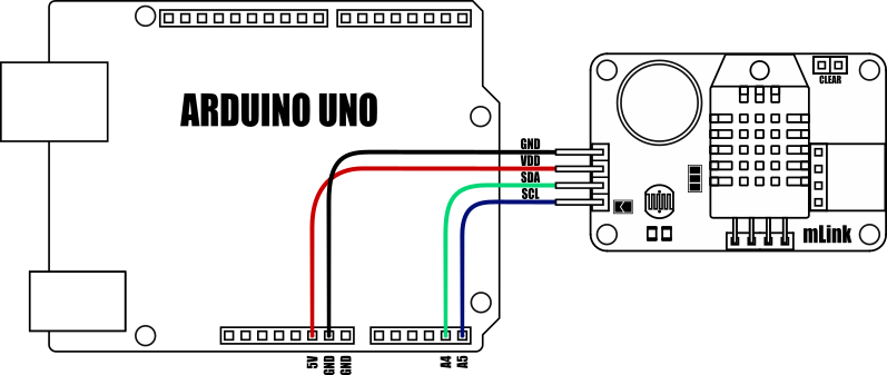
Because the modules use an I2C interface this also means multiple modules can be controlled from a single Arduino I2C interface simply by daisy-chaining them together. Note to control multiple mLink modules of the same type requires changing the default I2C address of the additional modules. See example Arduino sketch on forum post.

Image


Sensor read example

Arduino Sensor Read Example:

This sketch demonstrates how to read the module sensors. Note, to read the current temperature and humidity a new measurement must first be triggered. Once triggered the modules busy state can be checked to see when the measurement is complete (busy = false).

  1. #include "mLink.h"                              // Include the library
  2.  
  3. #define I2C_ADD 0x5B                            // Default I2C address
  4.  
  5. mLink mLink;                                    // Create an instance of the library
  6.  
  7.  
  8. void setup()
  9. {
  10.   Serial.begin(9600);
  11.   mLink.init();                                 // Initialise the library
  12. }
  13.  
  14.  
  15. void loop()
  16. {
  17.   mLink.HSense_Start_Meas(I2C_ADD);             // Trigger a new temp/hum measurement
  18.   while(mLink.busy(I2C_ADD));                   // Wait for the measurement to complete
  19.  
  20.   // Read the sensors
  21.   float temp = mLink.HSens_Temp(I2C_ADD);
  22.   float hum = mLink.HSens_Hum(I2C_ADD);
  23.   byte LDR = mLink.HSens_LDR(I2C_ADD);
  24.   boolean PIR = mLink.HSens_PIR(I2C_ADD);
  25.  
  26.   // Print out the results
  27.   Serial.print("Temperature: "); Serial.println(temp, 1);
  28.   Serial.print("Humidity: "); Serial.println(hum, 1);
  29.   Serial.print("Light: "); Serial.println(LDR);
  30.   Serial.print("PIR: ");
  31.   PIR ? Serial.println("Triggered!") : Serial.println("Idle");
  32.  
  33.   Serial.println();
  34.  
  35.   delay(1000);
  36. }

Sleep example

Sensor read with sleep example:

This sketch demonstrates how to use the modules low power sleep mode. The sketch will wake the module from sleep, trigger a temp/hum measurement, and when complete read the result before finally putting the module back to sleep again.

  1. #include "mLink.h"                              // Include the library
  2.  
  3. #define I2C_ADD 0x5B                            // Default I2C address
  4.  
  5. mLink mLink;                                    // Create an instance of the library
  6.  
  7.  
  8. void setup()
  9. {
  10.   Serial.begin(9600);
  11.   mLink.init();                                 // Initialise the library
  12. }
  13.  
  14.  
  15. void loop()
  16. {
  17.   mLink.wake(I2C_ADD);                          // Wake the module
  18.   mLink.HSense_Start_Meas(I2C_ADD);             // Trigger a new temp/hum measurement
  19.   while(mLink.busy(I2C_ADD));                   // Wait for the measurement to complete
  20.  
  21.   // Read the sensors
  22.   float temp = mLink.HSens_Temp(I2C_ADD);
  23.   float hum = mLink.HSens_Hum(I2C_ADD);
  24.  
  25.   mLink.sleep(I2C_ADD);                          // Put the module back to sleep
  26.  
  27.   // Print out the results
  28.   Serial.print("Temperature: "); Serial.println(temp, 1);
  29.   Serial.print("Humidity: "); Serial.println(hum, 1);
  30.  
  31.   Serial.println();
  32.  
  33.   delay(1000);
  34. }

Addres change example

Changing the modules I2C address:

This sketch will use the mLink library to change the I2C address of an mLink module.

To use this sketch set CURRENT_I2C_ADD to the current I2C address of your module. Then set NEW_I2C_ADD to the address you wish to change the address to.

Run the sketch and the result will be output to the serial monitor.

  1. #include "mLink.h"
  2.  
  3. mLink mLink;
  4.  
  5. #define CURRENT_I2C_ADD 0x5B    // Current I2C address
  6. #define NEW_I2C_ADD     0x5C    // New I2C address
  7.  
  8.  
  9. void setup()
  10. {
  11.   Serial.begin(9600);
  12.  
  13.   mLink.init();  
  14.  
  15.   // First check to made sure an mLink module at the new address does'nt alread exist
  16.   if(checkAddress(NEW_I2C_ADD))
  17.     Serial.println("Error: There is alread an mLink module at the new address!");
  18.   else
  19.   {
  20.     // If the new address is free, write it to the current module.
  21.     // But first we need to unlock the address register by writing
  22.     // 0x55 then 0xAA to it...
  23.     mLink.write(CURRENT_I2C_ADD, MLINK_ADD_REG, 0x55);
  24.     mLink.write(CURRENT_I2C_ADD, MLINK_ADD_REG, 0xAA);
  25.    
  26.     // ...then we can write the new address:
  27.     mLink.write(CURRENT_I2C_ADD, MLINK_ADD_REG, NEW_I2C_ADD);
  28.     delay(10);
  29.  
  30.     // Now check the new address to confirm it changed
  31.     if(checkAddress(NEW_I2C_ADD))
  32.       Serial.println("Address change worked!");
  33.     else
  34.       Serial.println("Error: Addrees change failed!");
  35.   }
  36. }
  37.  
  38. void loop()
  39. {
  40. }
  41.  
  42.  
  43. // Function checks an I2C address to see if there is an mLink module there
  44. boolean checkAddress(byte add)
  45. {
  46.   if(mLink.read(add, MLINK_ADD_REG) == add)
  47.     return true;
  48.   else
  49.     return false;
  50. }


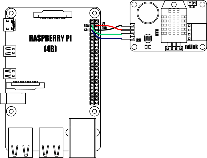
Raspberry Pi Connection Example:

Image


Sensor Read Example

Raspberry Pi Sensor Read Example:
This program demonstrates how to read the module sensors. Note, to read the current temperature and humidity a new measurement must first be triggered. Once triggered the modules busy state can be checked to see when the measurement is complete

This program requires the mLink Python library module to be installed. Please see the following forum thread for more information on how to install the Python module and requirements:

viewtopic.php?f=131&t=3062

  1. from mLink import mLink                     # Import the mLink module
  2. import time
  3.  
  4. ml = mLink.mLink(1)                         # Create an instance of the module
  5.  
  6. I2C_ADD = 0x5b                              # Default I2C address is 0x5b
  7.  
  8.  
  9.  
  10. ml.HSens_Clear_Trigs(I2C_ADD)               # Clear the PIR trigger counter
  11.  
  12. while 1:
  13.     ml.HSENS_Start(I2C_ADD)                 # Start a new DHT22 measurement
  14.    
  15.     while ml.busy(I2C_ADD):                 # Wait for measurment to complete
  16.         pass
  17.    
  18.     # If not DHT22 errors then print temperature and humidity
  19.     if ml.HSens_DHT22_Error(I2C_ADD) == False:
  20.         print("Temp = ", ml.HSens_Temp(I2C_ADD), "oC")
  21.         print("Hum  = ", ml.HSens_Hum(I2C_ADD), "%RH")
  22.     else:
  23.         print("DHT22 read error")
  24.    
  25.     # Print LDR light level
  26.     print("LDR  = ", ml.HSens_LDR(I2C_ADD))
  27.    
  28.     # Print PIR state
  29.     if ml.HSens_PIR(I2C_ADD):
  30.         print("PIR: TRIGGERED!")
  31.     else:
  32.         print("PIR: Idle")
  33.     print("Triggers: " + str(ml.HSens_Trigs(I2C_ADD)))
  34.    
  35.     print()
  36.    
  37.     time.sleep(1)


Other useful information:


Factory Reset:

Should you wish to restore the module back to its factory default configuration, this can be done by manually forcing a factory reset. All mLink modules include a set of pads labelled clear:

Image

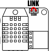
To perform a factory reset carefully link the two pads together with a piece of wire or with something conductive such as a paperclip. Whilst linked, connect power to the module via the VCC and GND connections. Wait a few seconds and then remove the short from the pads. The module's settings, including its I2C address, should now be restored back to factory defaults.


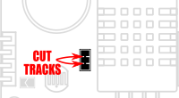
Removing I2C pullups:

If your development board already has pullups for its I2C interface fitted, or you wish to connect more than 5 mLink boards to the same I2C interface, then you can remove the pullups for the additional boards by cutting the tracks between the solder pads shown below.

Image


3.3V operation

If you wish to power this board via a 3.3V power supply you can bypass the onboard 5V regulator by linking the following pad with a solder bridge.

Image

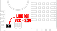
Once linked, the VDD input header pin will now require a 3.3V supply instead of 5V.

Note: When configured for a 3.3V supply this module can only be connected to additional mLink modules that are 3.3V compatible.


Dimensions:

Image


Image

mLink Arduino library

viewtopic.php?f=58&t=3001

Please note you will need at least V1.6 (07 Jan 2023) of the library to support this module. If you have an older version already installed please update it to the latest version.


mLink Raspberry Pi Python module
The mLink python module can be installed with the following terminal command:

  1. pip install hc-mlink

Alternatively the library can be manually installed by downloading it from the forum and unzipping it to your project folder. See the Python module forum thread for more information and download link:
viewtopic.php?f=131&t=3062&p=8592#p8592

Please note that in some cases there may be additional configuration required. If you have issues getting your Raspberry Pi to communicate with the mLink module then please see the Python module forum thread here: viewtopic.php?f=131&t=3062


mLink Specifications and Register Map
https://hobbycomponents.com/downloads/m ... er_Map.pdf


Libraries, example code, and diagrams are provided as an additional free service by Hobby Components and are not sold as part of this product. We do not provide any guarantees or warranties as to their accuracy or fitness for purpose.

Post Reply

Return to “mLink”