SmartRFy Sensor Module (HCMODU0141)
Posted: Sun Feb 23, 2020 1:14 pm


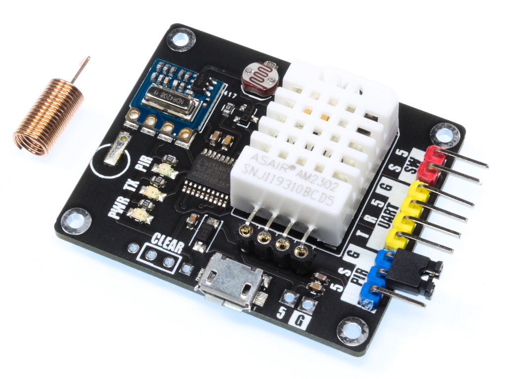
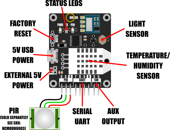
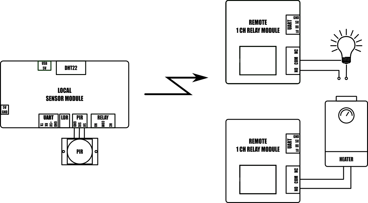
The SmartRFy sensor module adds the option to remotely monitor various sensors via a SmartRFy network connection. The sensor module includes a temperature and humidity sensor (DHT22) and has the ability to measure ambient light levels via an integrated photo-resistor. Out of the box the module will automatically transmit readings from these sensors once every 60 seconds (when reconfigured via the module serial port this can be changed from 10 to 65535 seconds) which can then be received by other SmartRFy devices with receive capability. For example remote sensor readings can be read directly into a computer via a SmartRFy USB module, or a SmartRFy relay module can be configured to trigger depending on sensor values transmitted from a remote sensor module.
The sensor module also includes a header for interfacing common types of 5V PIR motion detectors (see SKU: HCMODU0003). By default the sensor module will transmit the state of a connected PIR whenever its state changes. This transmitted state may then be used by any suitably configured remote SmartRFy module capable of receiving its data.
Additionally, the sensor module includes an auxiliary digital output (labelled SW). This pin can be reconfigured via the sensor module's serial interface to automatically trigger based on max and min values of one of the module's sensors.
Features

• Local and remote control via simple text based serial commands.
• Up to 255 zones and 255 addresses (default zone 0, address 0).
• Basic automation features (requires a USB to serial adaptor or microcontroller for configuration).
• Compatible with most microcontrollers featuring a serial UART interface.
• Wireless serial communication with 8 different baud rates (9600 default).
• Built-in temperature and humidity sensor (DHT22).
• Built-in light sensor (photoresistor).
• Automatically read and transmit temperature, humidity, and light levels (will transmit readings once every 60 seconds by default).
• Can automatically transmit state changes from a connected PIR sensor.
• Auxiliary digital output can be programmed to automatically trigger based on readings from any of the connected sensors and supports on/off, toggle, and timer modes.
Specification
Model number: HCMODU0141
Supply Voltage: 4.5 to 5.5V
Supply current min: 9.5 mA (idle)
Supply current max: 21 mA (transmit)
Operating frequency: 433MHz (OOK)
Operating range: 30 Meters (unobstructed)
Temperature sensor range: -40 to 80 oC
Temperature sensor resolution: 0.1oC
Humidity sensor range: 0 to 10 %RH
Humidity sensor resolution: 0.1 %RH
LDR sensor range: 0 to 255
PIR input (S) pin characteristics: Input logic low voltage: -0.3V to Vdd x 0.3V
Input high voltage Vdd x 0.7 to Vdd + 0.3V
Aux digital output (SW0): Open collector with 10K pullup. 100mA max sink current
Interfaces: RF Tx, serial UART, PIR, and relay Aux digital output
Module dimensions (WxDxH): 44.2 x 36.6 x 20mm
SmartRFy system overview
SmartRFy modules are a range of wireless modules that provide a simple low cost way of controlling and monitoring remote devices and sensors. They are designed to work at their basic level with no programming required. However, when reconfigured or controlled via their serial interface they can also provide more complex and even autonomous functions.
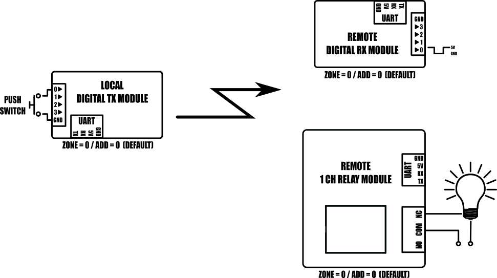
SmartRFy modules work by wirelessly communicating with one another using simple text based commands - for example, to turn on a remote relay a command such as RLY=1 can be sent, and to turn it back off RLY=0. These commands can be automatically sent from one module to another or can be sent by a user via a modules serial interface to manually control modules on the SmartRFy network.
They are addressable and can be grouped into one of 255 zones, with each zone capable of individually addressing 255 devices, giving a total of over 65,000 unique addresses. SmartRFy modules are designed to be both easy and flexible to use by providing three levels of control:
Zero configuration (out-of-the-box)

With no configuration at all the SmartRFy range of modules allow basic functionality such as remotely switching relays, digital pins, or monitoring sensors, such as temperature, humidity, light, motion etc. All SmartRFy modules default to the same zone and address and so can respond to, or control, other modules without the need to modify any zone or address settings.
Serial port configuration

All smartRFy modules include a serial port which allows them to be re-configured using simple text based commands. These text commands allow changing of configuration settings and control of specific features of each module. Any setting changes are stored by the module's non-volatile memory and so are retained even when power is removed from the module. When reconfigured they are able to perform more complex functions and even some basic autonomous tasks. For example, a SmartRFy relay module can be reconfigured to control a heating system based on the temperature transmitted from a remote sensor or, turn on a flood light for a set amount of time when triggered by a remote PIR – all without any additional hardware. Serial port configuration also allows a modules zone and address (all SmartRFy modules default to zone and address 0) to be changed. This provides the option for modules to be placed into groups, which will then only respond to other modules with a matching zone or address.
Slave controlled

Example 1: Turning on a remote relay with zone = 1 and address = 5

Example 2: Send plain serial text “Hello” to a remote microcontroller
SmartRFy modules can also be controlled via their serial port by other devices such as microcontrollers or computer based automation software such as Node-RED. Using a SmartRFy module as a slave device (must be capable of transmitting/receiving) gives a master device the ability to monitor and control any other SmartRFy devices on the network regardless of their zone and address. SmartRFy modules can even be used as a passive wireless serial port for passing non-SmartRFy data to other remotely connected devices.

SmartRFy Sensor Module Manual
https://hobbycomponents.com/downloads/s ... l_V1_1.pdf
Libraries, example code, and diagrams are provided as an additional free service by Hobby Components and are not sold as part of this product. We do no provide any guarantees or warranties as to their accuracy or fitness for purpose.
Descriptions and diagrams on this page are copyright Hobby Components Ltd and may not be reproduced without permission.