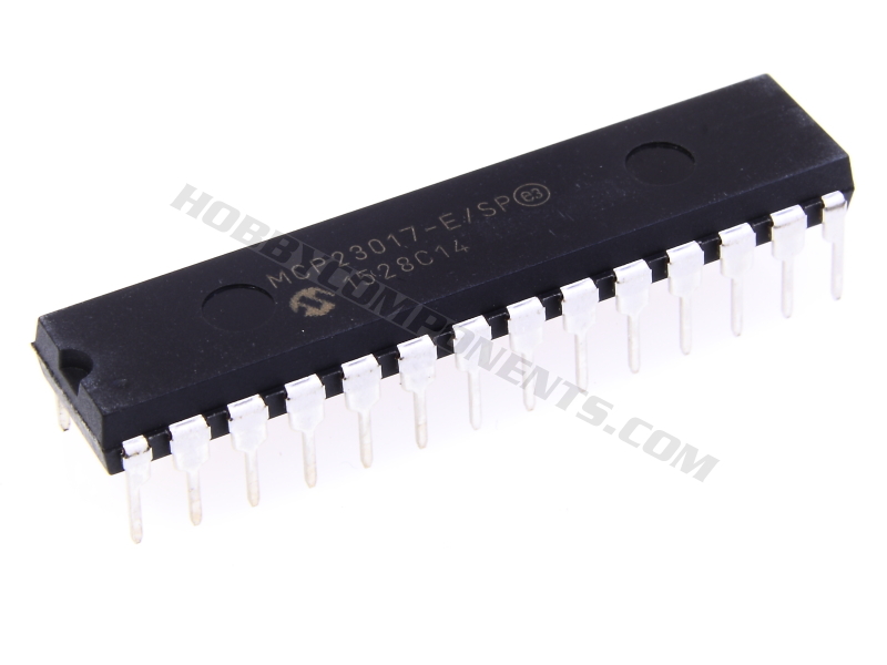

The MCP23017 (HCCOIC0048) IC provides 16-bit, general purpose parallel I/O expansion for I2C bus applications. It consists of multiple 8-bit configuration registers for input, output and polarity selection. The system master can enable the I/Os as either inputs or outputs by writing the I/O configuration bits (IODIRA/B). The data for each input or output is kept in the corresponding input or output register. The polarity of the Input Port register can be inverted with the Polarity Inversion register. All registers can be read by the
system master. The 16-bit I/O port functionally consists of two 8-bit ports (PORTA and PORTB). The MCP23017 can be
configured to operate in the 8-bit or 16-bit modes.
There are two interrupt pins, INTA and INTB, that can be associated with their respective ports, or can be logically OR’ed together so that both pins will activate if either port causes an interrupt. The interrupt output can be configured to activate under two conditions (mutually exclusive):
The device has 3 configurable I2C slave address pins allowing for multiple devices to be connected to the same I2C bus. Finally a very wide operating voltage range means the MCP23017 can be directly interfaced to both 3.3V and 5V devices.


Features:
- • 16-bit remote bidirectional I/O port
- I/O pins default to input
• High-speed I2C™ interface (MCP23017)
- 100 kHz
- 400 kHz
- 1.7 MHz
• High-speed SPI interface (MCP23S17)
- 10 MHz (max.)
• Three hardware address pins to allow up to eight
devices on the bus
• Configurable interrupt output pins
- Configurable as active-high, active-low or
open-drain
• INTA and INTB can be configured to operate
independently or together
• Configurable interrupt source
- Interrupt-on-change from configured register
defaults or pin changes
• Polarity Inversion register to configure the polarity
of the input port data
• External Reset input
• Low standby current: 1 µA (max.)
• Operating voltage:
- 1.8V to 5.5V @ -40°C to +85°C
- 2.7V to 5.5V @ -40°C to +85°C
- 4.5V to 5.5V @ -40°C to +125°C
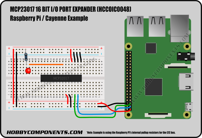
Raspberry Pi users:
For Raspberry Pi uses we have tested this device with the free Cayenne cloud based IoT software platform. Simply connect the it to your Raspberry Pi as shown below and use the Cayenne software platform to control the I/0 pins an interface to digital hardware.
You can create a free account simply by clicking our referral link below:

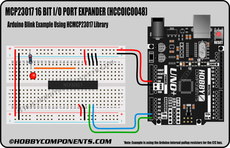
Arduino users:
To make using this device with your Arduino as easy as possible we have written an exclusive library (HCMCP23017). This library can be downloaded from the software section of our support forum here:
http://forum.hobbycomponents.com/viewto ... =58&t=2041
The library will allow you to configure and control the 16 I/O pins using pin single pins and port functions.
Example 'blink' sketch using the HCMCP23017 library:
Code: Select all
/* FILE:    HCMCP23017_Pin_Blink_Example
   DATE:    24/06/16
   VERSION: 0.1
   AUTHOR:  Andrew Davies

   Sketch created by Hobby Components Ltd (HOBBYCOMPONENTS.COM)

24/06/16 version 0.1: Original version

This example sketch demonstrates how to use the HCMCP2017 library to change the
output state of one of the 16 I/O pins (GPA0/Pin 21) on the MCP23017. The sketch
will continually change the state from high to low with a 1 second select between
each change. Currently supported products:

MCP23017 Serial 16 bit Expander IC (HCCOIC0048)

Arduino Connections:

Uno/Nano............MCP23017 (DIP)
+5V.................VDD (Pin 9)
GND.................VSS (Pin 10)
A4..................SDA (Pin 13)
A5..................SCL (Pin 13)

This sketch also assumes the slave 3 address pins (A0-A2) on the MCP23017
are pulled low.

Please note that if you intend to connect an LED to the I/O pin a suitable
current limiting resistor must be included.

You may copy, alter and reuse this code in any way you like, but please leave
reference to HobbyComponents.com in your comments if you redistribute this code.
This software may not be used directly for the purpose of selling products that
directly compete with Hobby Components Ltd's own range of products.

THIS SOFTWARE IS PROVIDED "AS IS". HOBBY COMPONENTS MAKES NO WARRANTIES, WHETHER
EXPRESS, IMPLIED OR STATUTORY, INCLUDING, BUT NOT LIMITED TO, IMPLIED WARRANTIES OF
MERCHANTABILITY AND FITNESS FOR A PARTICULAR PURPOSE, ACCURACY OR LACK OF NEGLIGENCE.
HOBBY COMPONENTS SHALL NOT, IN ANY CIRCUMSTANCES, BE LIABLE FOR ANY DAMAGES,
INCLUDING, BUT NOT LIMITED TO, SPECIAL, INCIDENTAL OR CONSEQUENTIAL DAMAGES FOR ANY
REASON WHATSOEVER.
*/

/* Include the HCMCP23017 library */
#include <HCMCP23017.h>

/* Create an instance of the library and set the I2C slave address */
HCMCP23017 HCMCP23017(0x20);

void setup()
{
  /* Initialise the library */
  HCMCP23017.Init();

  /* Set the pin to an output */
  HCMCP23017.pinDir(GPA0, PIN_OUTPUT);
}

void loop()
{
  /* Pull the pin high */
  HCMCP23017.pinWrite(GPA0, HIGH);
  delay(1000);
  /* Pull the pin low */
  HCMCP23017.pinWrite(GPA0, LOW);
  delay(1000);
}

The HCMCP23017Arduino compatible library required for the above sketch can be downloaded from the software section of our support forum here:
http://forum.hobbycomponents.com/viewto ... =58&t=2041
Disclaimer: The Cayenne platform is an external free service and is not provided by, or connected to, Hobby Components Ltd. It is therefore not being sold as part of the product advertised on this page. As such we do not provide any guarantees or warranties with regards to this service. Issues or questions related to the Cayenne platform should be directed to Cayenne and not Hobby Components Ltd.
Libraries, example code, and diagrams are provided as an additional free courtesy by Hobby Components and are not sold as part of this product. We do no provide any guarantees or warranties as to their accuracy or fitness for purpose.
Descriptions and diagrams on this page are copyright Hobby Components Ltd and may not be reproduced without permission.