
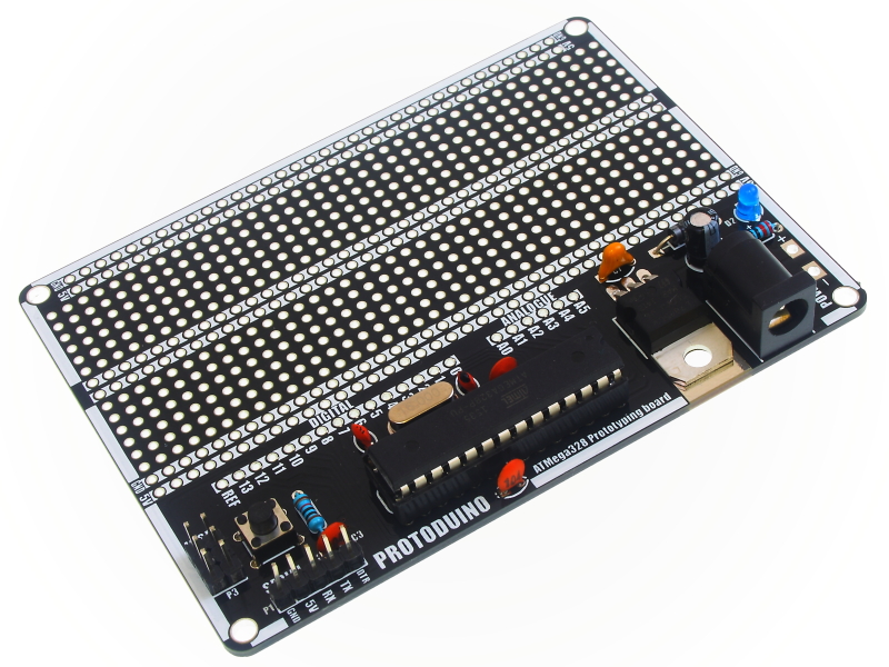
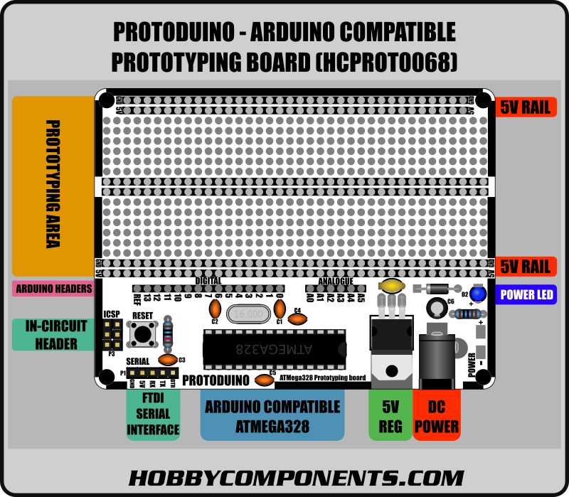
Designed as a means to easily go from your Arduino and breadboard prototype to a more permanent design, the Protoduino is a development board consisting of an Arduino compatible ATMega328P with bootloader and a large prototyping area with a similar layout to a standard breadboard. The kit consists entirely of through-hole components, making it easy to construct, even for someone with basic soldering skills. It also provides an on-board 5V regulated power supply which is available on two 5V and GND power supply rails on the prototyping area. All of the standard Arduino interface pins (D0 - D13 & A0 to A5) are brought out to a set of pads conveniently placed near the prototyping area.
For programming, the microcontroller can be programmed via an FTDI compatible serial header (via the bootloader, select Nano as the board type), or directly using the ICSP header and a suitable ICSP programmer.

Item number (Black): HCPROT0068_BLK
Power (via DC Socket): 7.5 - 12V
Power (via Vcc pin): 5 - 5.5V
Dimensions: 100mm x 75mm
Prototyping area: 38 x 18 grid (674 holes in total)
Build Guide:
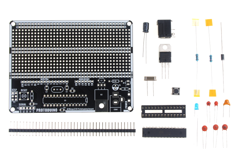
Required Tools:
Soldering iron.
Solder.
A pair of snips for trimming component legs.
A pair of long nose pliers to bend relevant component legs.
Soldering tip: When soldering components to a circuit board it is always best to start with the smallest components first. This helps keep the board flat and stops access to pads from being restricted by larger components. The first step is to start by soldering the small components such as resistors, capacitors, and diode. When soldering the components with multiple pins such as ICs it is recommended to solder the two opposite corner pins first. You can then check that the component is flat and if not just heat one of the soldered pads and gently push the component against the PCB to make it flat. Once you determined that the component is flat against the PCB the other pads can be soldered.
Important notes:
For some components the orientation of the component is important. These components will be highlighted in the build guide. When constructing the PCB all components should be fitted to the upper side of the PCB.
RESISTORS
All resistors in the kit are coloured light blue and will have a series of five coloured bands. The band colours signify the value of the resistor. When fitting these resistors the orientation of the resistor is not important.
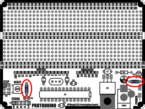
Solder the 1K Ohm resistor (Brown, Black, Black, Brown, Brown) to footprint R2.
Solder the 10K Ohm resistor (Brown, Black, Black, Red, Brown) to footprint R1.
Use a pair of snips to trim any excess components legs protruding from the opposite side of the PCB
DIODE
The diode is a small black cylindrical component with a silver band at one end. The band denotes the negative end (cathode) of the component. When placing the diode make sure that the silver band faces the bottom of the PCB as shown in the image below.
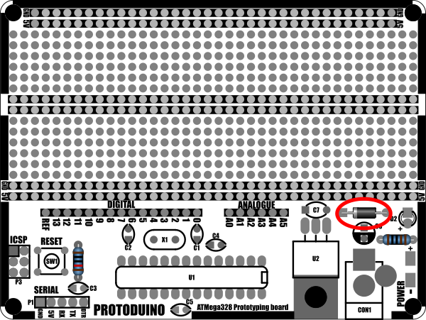
Solder the diode to footprint D1 and use a pair of snips to trim any excess component legs protruding from the opposite side of the PCB.
CAPACITORS - CERAMIC
All the ceramic capacitors in this kit are a small light brown disc shape. A number on the side of the capacitor can be used to determine their value. When fitting these capacitors the orientation is not important.
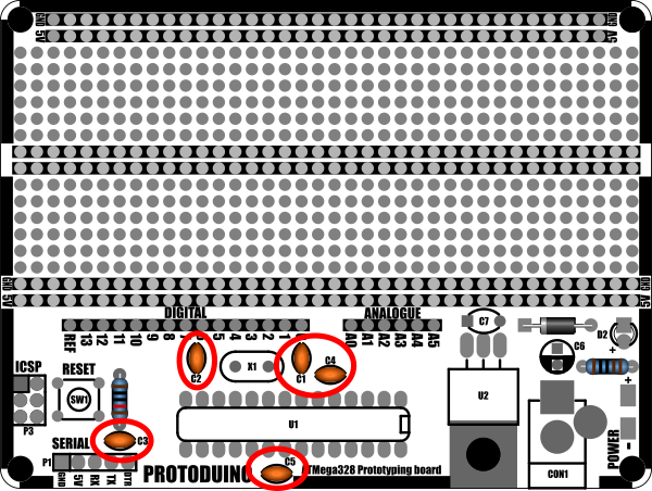
Solder the two 22pF (usually marked with the number 22) to footprints C1 & C2
Solder the three 100nF (usually marked with the number 104) to footprints C3, C4, & C5.
Use a pair of snips to trim any excess component legs protruding from the opposite side of the PCB.
16MHZ CRYSTAL
The crystal is an oval silver metal can with the number 16.000 engraved on the top. When fitting the crystal the orientation is not important.
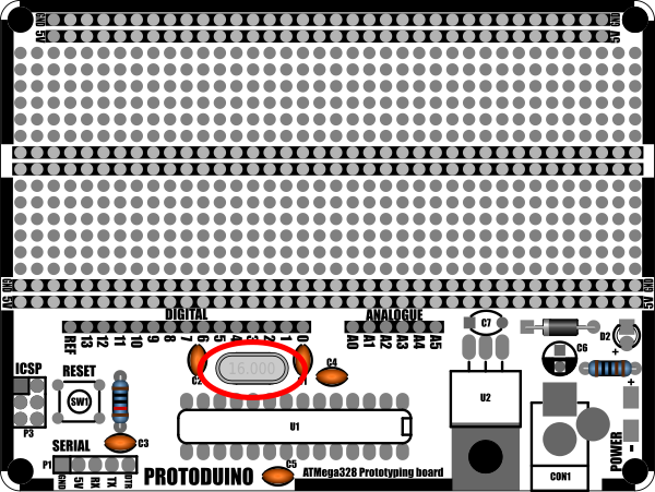
Solder the crystal to footprint X1 and use a pair of snips to trim any excess component legs protruding from the opposite side of the PCB.
IC SOCKET
The IC socket is the holder that the ATMega328 will be inserted into. When installing the socket there is a small notch at one end. The socket should be orientated so that this notch is on the same end as the back silkscreen tab on the footprint.
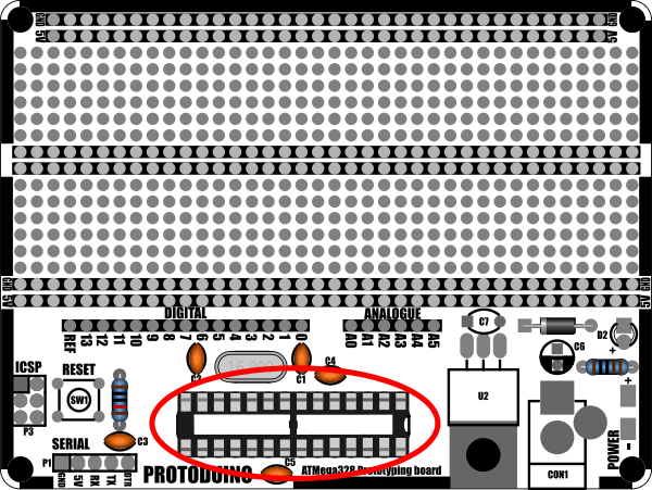
Solder the 28 pin IC socket to footprint U1.
3MM POWER LED
The 3mm blue LED is used as a power indicator. The orientation of this LED is important. You can identify the negative pin (cathode) as it is slightly shorter than the positive (anode) one. When placing the LED the shorter negative pin should be positioned to the flat edge on the PCB footprint.
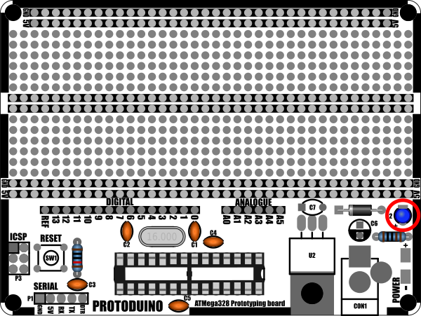
Solder the 3mm LED to footprint D2 and use a pair of snips to trim any excess component legs protruding from the opposite side of the PCB.
PUSH BUTTON
The push button in the kit is used as a reset for the microcontroller. It is a small square silver and black component with four legs. The orientation of this switch is important. Position it so that the orientation of the legs matches the diagram below.
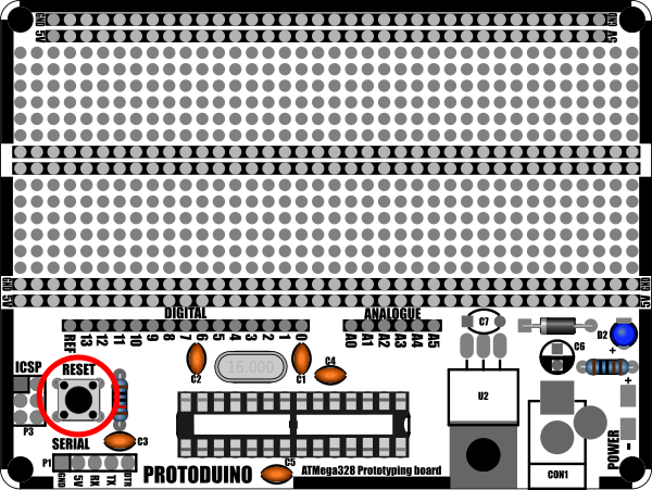
Solder the push button to footprint SW1.
REGULATOR
Before fitting the regulator, its pins need to be bent so that the regulator sits flat to the PCB. Do this by bending the pins about half way down using a pair of long nose pliers so that when the regulator is inserted into the PCB the metal tab at the top of the regulator lays flat against the heatsink pad.
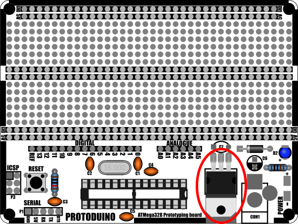
Solder the regulator to footprint U2 and use a pair of snips to trim any excess component legs protruding from the opposite side of the PCB. You can also optionally solder the tab of the regulator to the large square pad beneath it.
HEADER PINS
There are two headers, a 5 pin header for the serial interface, and a 2 x 3 pin straight header that makes up the 6 pin ICSP header. For both headers, they may be provided in the kit as on continuous strip of pins. You can simply snap this strip into appropriate lengths using a pair of long nose pliers.
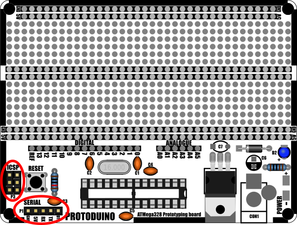
Solder the 5 pin header to footprint P1.
Solder the two 3 pin header pins to footprint P3.
POWER SUPPLY CAPACITORS
There are two capacitors required for the power supply circuit and they are of different types. The first one is a yellow ceramic 470nF capacitor which can be identified by the number 474 printed on the side. The orientation of this capacitor is not important. The second capacitor is a black or blue 100uF cylindrical electrolytic capacitor and has a silver/grey stripe on one side. The stripe denotes the negative pin of the capacitor. The orientation of this capacitor is important, see diagram for correct orientation.
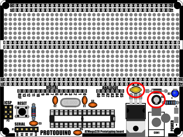
Solder the ceramic capacitor to footprint C7.
Solder the electrolytic capacitor to footprint C6.
Use a pair of snips to trim any excess component legs protruding from the opposite side of the PCB.
DC POWER CONNECTOR
The DC power connector is a back plastic 3 pin socket which should be positioned so that the socket is facing the outside of the PCB.
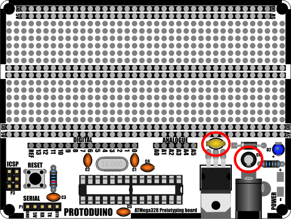
Solder the 2.1mm DC socket to footprint CON1.
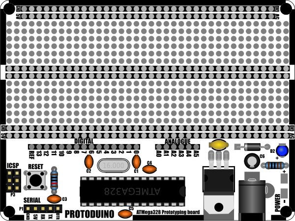
INSERT THE IC
All the components that require soldering should now be soldered to the PCB. The final step is to insert the IC into the IC socket. The orientation of the IC is important. At one end of the IC there will be either a notch and/or a small circle cut into the IC package. When inserting the IC make sure it is orientated so that this end is at the same end as the black silkscreen tab on the footprint.

Schematic: https://hobbycomponents.com/downloads/H ... ematic.pdf