1)How would i get to switch on/off all motors at the same time?
It's important to to first understand that stepper motors work in a different way to normal DC motors. You can't just apply a voltage across them to make them rotate like you would do with a DC motor. They instead need a sequence of pulsed voltages applied to each of their coils in a sequence to make them rotate. This is done by use of a stepper motor driver board. If you wish to use stepper motors like the one in this forum they need to be connected to one of these drivers which will generate the pulses to the motor for you. We do sell several types of driver suitable for this type of motor but if you want a belt and braces solution then you may want to look at our TB6560 driver here:
http://forum.hobbycomponents.com/viewto ... 6560#p2687
Most stepper motor controller like the one in the link above tend to work in the same way. They usually have 3 control inputs, a step, direction and enable input:
Step input: By pulsing a voltage (5V) on this input causes the stepper motor to turn by a small increment.
Direction: Applying 5V to the direction input will cause the motor to turn in one direction each time the step input is pulsed, applying 0V will cause it to turn in the opposite direction.
Enable: Applying either 5V or 0V will enable or disable drive to the motor.
So to answer the above question you can just switch 5V to the enable input.
2)Keep them all at the same speed?
So long as the pulse to the step input of each controller occurs at the same time, each motor will rotate at exactly the same speed. This is one of the advantages of using a stepper motor over an ordinary DC motor.
3)From a single switch and be mains powered?
As mentioned above, you would normally use a microcontroller to generate the 3 signals required for the driver boards such as one of the Arduino boards we sell. If you have any experience of using these boards you can even do something like using a combination of Arduino Uno and LCD shield to have and LCD and push button control interface.
Can someone please up a diagram of what this circuit should look like as well as give a rundown of tools and equipment needed?
There is a simplified diagram in the driver board link above that will give you an idea or how the motor is connected.
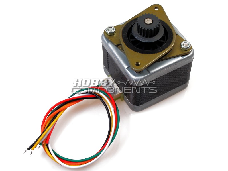
I noticed that there are bear wires in this image; but other motors have a red plastic connector - I know nothing about this will my motor come ready connected or do I have to do this myself?
These motors are supplied with bare wires, but notice that the driver board in the link above has screw terminal blocks.
What do the different coloured wires mean?
The wires are connected to the +ve and -ve sides of the motor's coils labelled A+, A-, B+, B-. There is a description of each wire in the first post of this thread. You'll see on the TB6560 controller there are similar labelled terminals.