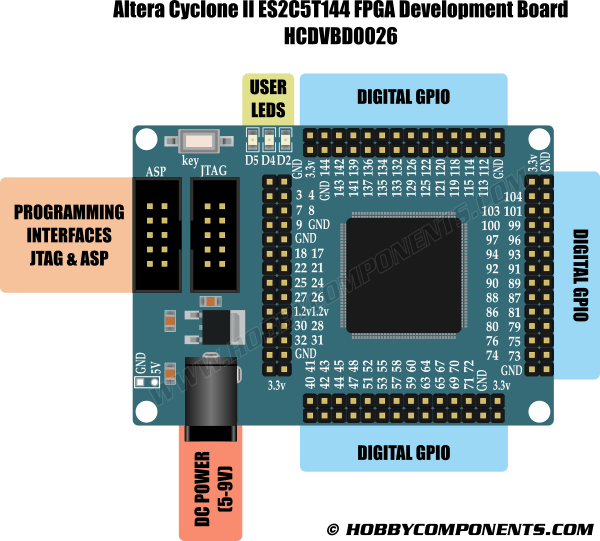

This development board is a low cost way to get into the world of FPGAs and programmable logic. Based on a 144 pin Altera Cyclone II (EP2C5ST144C8N) device this board is a significant step up from our popular MAX II CPLD development board (HCDVBD0006). It features standard 0.1" pitch breakout headers for the devices 89 usable I/O cells, on-board 50MHz crystal oscillator which provides the FPGA's internal clock source, on-board 3.3V & 1.2V regulators with 2.1mm DC power socket, user LED's and both JTAG and ASP with EPCS device programming headers which are directly compatible with our Altera USB programmer (see item HCDVBD0007).

Board Features:
Breakout headers for all usable I/O
On-board 3.3V & 1.2V regulators.
Single 5V power source via 2.1mm DC socket
3x programmable user LEDS connected to pins 3, 7 & 9
Power LED
On-board 50MHz oscillator connected to pin 17
Reset button
JTAG interface
ASP serial programming interface with on board EPCS4 storage
Compatible with the Altera Quartus 2 and free web edition software
FPGA Features:
Number of Logic Elements: 4608 (16 LE's per block)
Number of 4K bit memory blocks: 26 (119,808 total bits)
Number of embeded multipliers: 13 (can be configured as 2 x 9 bit or 1 x 18 bit)
Number of PLL's: 2
Maxium usable IO: 89
Please note: Depending on your design, FPGAs can consume a large amount of power. If you have a complex design it may exceed the capabilities of the on-board regulators. In this case you should power the development board via the power header pins.
Recommended accessories:
Hobby Components Altera Blaster compatible CPLD/FPGA programmer: http://hobbycomponents.com/featured/273 ... compatible

USB to 2.1mm power lead: http://hobbycomponents.com/cables/789-1 ... -jack-plug

Software tools:
Altera Quartus II Web Edition (13.0) http://dl.altera.com/13.0sp1/?edition=w ... rm=windows
Altera Quartus Prime Lite Edition (15.1) http://dl.altera.com/15.1/?edition=lite
Verilog 'Blink' Example:
Code: Select all
module ledtest(sys_clk,led);

input sys_clk;
output [2:0] led;
reg	[25:0] count;
reg [2:0] led = 3'b101;

always @(posedge sys_clk)
	begin
		count <= count + 1;
		if(count == 26'b11_1111_1111_1111_1111_1111_1110)
			begin
			led <= ~led;
			end
		else
			led <= led;
	end

endmodule
Schematic
FAQ:
Each time i remove power my design is lost, how can I permanently program the FPGA?
The FPGA has no non-volatile storage capability. This is actually normal for these types of devices. However this development board does include an EPCS (EPCS04) IC. This is a custom device which is designed to store your design and then program the FPGA automatically as power is applied to the board. To program the EPCS device follow these steps:
1) Connect your programmer to the ASP header instead of the JTAG header. This will connect your programmer to the EPCS device instead of the FPGA
2) Open up the programmer window in Quartus (Tools->programmer) and in the window that opens up select 'Active Serial Programming' instead of JTAG for the programmer mode.
3) Next click the 'Add device button' and a new window will open. Under the Device name list check the 'EPS4' check box and then close the window by clicking the OK button.
4) In the main programmer window click the 'Change File' button and in the window that opens up navigate to your project area and select the file containing your design. Note that when programming the EPCS device you will need to select the file ending in .pof instead of the .sof file used for programming the FPGA.
5) In the main programmer window you can now check the program, verify, blank check, examine, or erase check boxes as required.
Disclaimer: Libraries, example code, and diagrams are provided as an additional free service by Hobby Components and are not sold as part of this product. We do no provide any guarantees or warranties as to their accuracy or fitness for purpose.
Descriptions and diagrams on this page are copyright Hobby Components Ltd and may not be reproduced without permission.