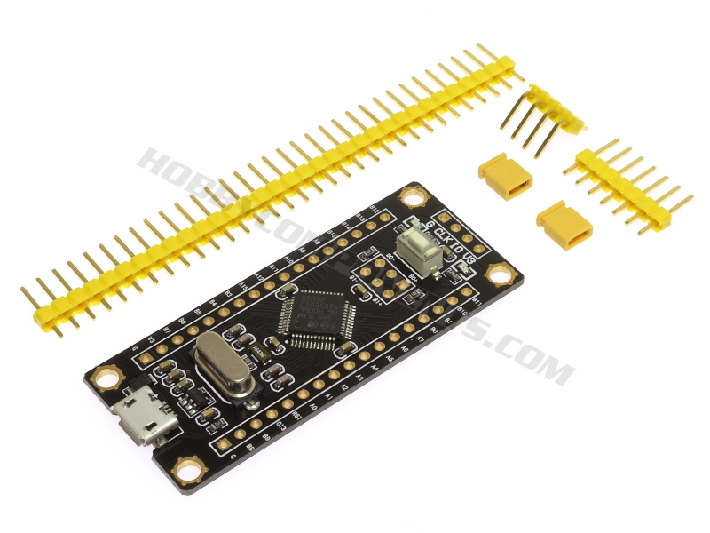

The STM32F103C8T6 (HCDVBD0033 / Black pill) Development Board is a low cost but feature rich alternative to an Arduino. The board features an ST Microelectronics STM32F103C8 Arm microprocessor running at a 72MHz clock speed. Coupled with 64K of Flash and 20K of SRAM this development board provides a powerful alternative to an Arduino. This development board is also not short on peripherals with 30 I/O pins, 14 of which can be configured as 12 bit ADC inputs, 12 as PWM with most pins being 5V tolerant. Supplied with the module are a set of 0.1" pitch headers (require soldering) which provide the option or breadboard mounting it with easy connection of standard Dupont cables.
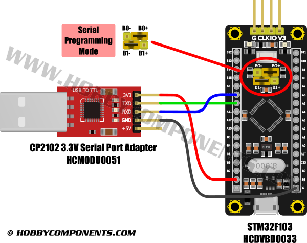
For programming there is the option of using the STLink download adapter (see item HCDVBD0016) or a standard USB to 3.3V TTL adapter (see item HCMODU0051). Support for this board can be added to the Arduino IDE via the board manager feature. See the following blog post for full instructions on how to quickly get up and running here:
http://blog.hobbycomponents.com/?p=703
Please note that this development board is the original STM32F103 based 'black pill' development board and not the STM32F401 or F411 based development board which is also unofficially referred to as the 'black pill' development board.
Feature comparison to Pro Mini:
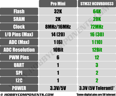
Specification:
Part number: HCDVBD0033
Power: 3.3V or 5V via microUSB
Processor: ST Microelectronics STM32F103C8
Flash memory: 64K
SRAM: 20K
I/O (MAX): 30
Analogue pins: 14
PWM pins: 12
UART: 3
SPI: 2
I2C: 2
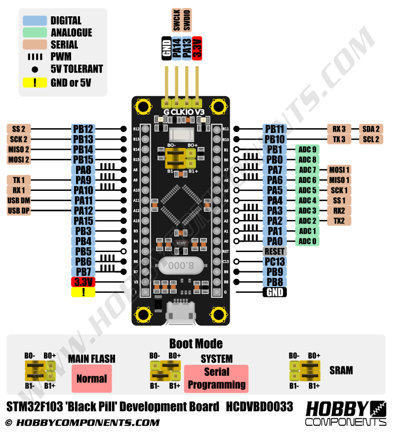
Pinout:
Programing via serial bootloader with Arduino IDE:
Example Arduino 'blink' sketch:
Code: Select all
#define LED_PIN PB12

void setup()
{
  pinMode(LED_PIN, OUTPUT);
}

void loop()
{
  digitalWrite(LED_PIN, HIGH);
  delay(1000);
  digitalWrite(LED_PIN, LOW);
  delay(1000);
}
FAQ:
When I configure pins PB3 & PB4 as inputs/outputs they don't seem to work. What am I doing wrong?
Pins PB3 & PB4 also function as JTAG debug pins. Ast his debug mode is tuned on by default you will need to disable it to use these pins as general purpose IO pins. You can do this by adding the following line to the top of setup() function in your Arduino sketch:
Code: Select all
afio_cfg_debug_ports(AFIO_DEBUG_SW_ONLY);Disclaimer: Libraries, example code, and diagrams are provided as an additional free service by Hobby Components and are not sold as part of this product. We do not provide any guarantees or warranties as to their accuracy or fitness for purpose.
Descriptions and diagrams on this page are copyright Hobby Components Ltd and may not be reproduced without permission.