Page 1 of 4
DS1302 Real Time Clock Module (HCMODU0035)
Posted: Sun Sep 08, 2013 10:23 am
by admin
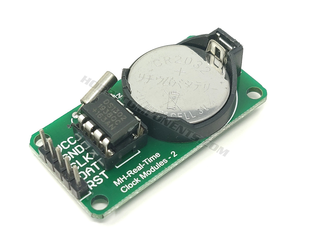

The DS1302 RTC is a compact real time battery backed clock module capable of accurately keeping the current time and date. It includes a 24 hour clock consisting of hours, minutes & seconds and a calendar which stores the current year in 2 digits, month and date. The calendar is also capable of correcting for months with different amounts of days and leap years. Additionally there is a day of the week counter to keep track of the current date.
Besides keeping track of the time and date the module also includes 31 bytes of RAM that is free to be used by the end users application. This makes it useful as an additional memory storage area or to store temporary data in applications where the microcontroller is reset or placed into deep sleep modes.
The module includes a CR2032 button cell which maintains the clock and RAM when power is removed from the modules header.
EXCLUSIVE LIBRARY:
For Arduino users we have written an exclusive library (HCDS1302) that gives access to these features. See link at the bottom of this post.
FEATURES:
Real-Time Clock Counts Seconds, Minutes, Hours, Date of the Month, Month, Day of the Week, and Year with Leap-Year Compensation Valid Up to 2100
31 x 8 Battery-Backed General-Purpose RAM
Serial I/O for Minimum Pin Count
2.0V to 5.5V Full Operation
Uses Less than 300nA at 2.0V
Single-Byte or Multiple-Byte (Burst Mode)
Data Transfer for Read or Write of Clock or RAM Data
Simple 3-Wire Interface
TTL-Compatible (VCC = 5V)
Optional Industrial Temperature Range: -40°C to +85°C
DS1202 Compatible
PINOUT:
VCC……………..2 to 5.5V
GND………..…...GND
CLK/SCK……Clock
DAT/IO………..Data
RST/CE………..Chip enable
Note pin order may vary
Example sketches:
Downloads:
DS1302.pdf
ARDUINO HCDS1302 LIBRARY:
The HCDS1302 library can be downloaded from the software section of this forum here:
viewtopic.php?f=58&t=3095&p=8713
Diagrams, libraries, and example code are provided as an additional free service by Hobby Components and are not sold as part of this product. We do no provide any guarantees or warranties as to their accuracy or fitness for purpose.
Descriptions and diagrams on this page are copyright Hobby Components Ltd and may not be reproduced without permission.
Re: DS1302 Real Time Clock Module (HCMODU0035)
Posted: Thu Nov 28, 2013 1:34 pm
by jackbell16
Hi,
how should I connect this RTC to Arduino Uno ?
Re: DS1302 Real Time Clock Module (HCMODU0035)
Posted: Fri Nov 29, 2013 11:21 am
by andrew
Connection to an Uno is as follows:
MODULE ARDUINO
GND -> GND
VCC -> +5V
SCK -> D4
I/O -> D3
RST(CS) -> D2
Re: DS1302 Real Time Clock Module (HCMODU0035)
Posted: Thu Dec 12, 2013 3:42 pm
by normski001
can you advise how i connect this to my HCARDU0036 rev 3 mega AT2560-16AU please
i am having a problem finding pin 2, 3, and 4
Re: DS1302 Real Time Clock Module (HCMODU0035)
Posted: Thu Dec 12, 2013 7:05 pm
by andrew
You should be able to connect it as per Uno pinout above
Re: DS1302 Real Time Clock Module (HCMODU0035)
Posted: Thu Dec 12, 2013 7:11 pm
by normski001
andrew wrote:You should be able to connect it as per Uno pinout above
i do not have d2, d3, d4 pins
here is my board
http://www.hobbycomponents.com/images/f ... pinout.jpg
Re: DS1302 Real Time Clock Module (HCMODU0035)
Posted: Thu Dec 12, 2013 7:22 pm
by andrew
Ok I see the confusion D2, D3, & D4 refer to the digital pins that are just labeled 2,3, & 4 on your board where it says PWM
Re: DS1302 Real Time Clock Module (HCMODU0035)
Posted: Thu Dec 12, 2013 7:56 pm
by normski001
i have just plugged the screen in them the outer holes 2 and 3 seem connected but not 4 on the display shield board
the 5v and gnd is also connected to outer holes on board.
the board and holes seem to be 2, 3, 11, 12, 13 pins connected to the empty display shield holes so no idea how i get to 4 for the rtc
on the lcd display i have D0 to D7 where i can putpins and d4 does go to the pin 4 you said, could i fix it there any advice would be help full please
Re: DS1302 Real Time Clock Module (HCMODU0035)
Posted: Fri Dec 13, 2013 11:23 am
by andrew
As you have a Mega would it be easier for you to use some of the other spare digital pins? Digital pins numbered 14 to 53 are not covered by the shield and so all you would need to do is change the pin assignment in the sketch. For example, in the example sketch in the first post find the following lines...
#define SCK_PIN 4
#define IO_PIN 3
#define RST_PIN 2
...and change the numbers to what ever digital pin numbers you use on your mega. Is this a solution or do you need to connect to the shield for some reason?
Re: DS1302 Real Time Clock Module (HCMODU0035)
Posted: Fri Dec 13, 2013 1:41 pm
by normski001
here is what i have done, gnd and +5v from top and bottom of digital pin block right of board, sck to pin 22 i/o to pin 24 rst to pin 26
/* Define the DIO pins used for the RTC module */
#define SCK_PIN 22
#define IO_PIN 24
#define RST_PIN 26
when i load program above i get error
DS1302 rtc(RST_PIN, IO_PIN, SCK_PIN); this line goes yellow
below box goes orange and says DS1302 does not name a type
then lines in black box
sketch_dec13b:46: error: 'DS1302' does not name a type
sketch_dec13b.ino: in function 'void setup()':
sketch_dec13b:51: error: 'rtc' was not declared in the scope
sketch_dec13b.ino function 'void loop()':
sketch_dec13b:64: error: 'rtc' was not declared in the scope
sketch_dec13b:64: error:'MONDAY' was not declared in the scope