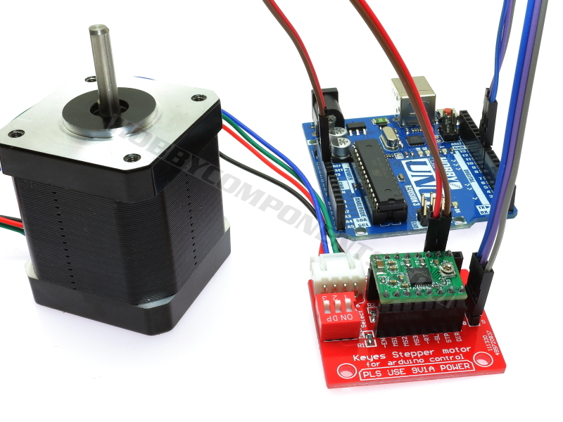

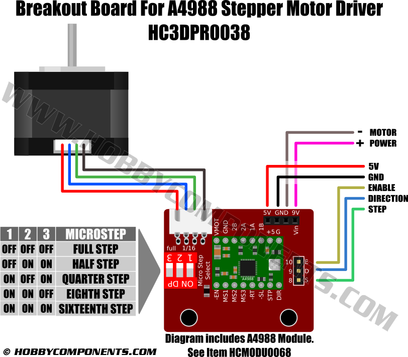
This item (HC3DPR0038) is a breakout out / adapter board for the low cost A4988 stepper motor driver board. It has a number of connectors that allow for easy interface of a stepper motor, power, and control signals to the A4988 driver module. Header sockets are provided so that the driver module can be easily inserted and removed from the breakout board. Standard 0.1" pitch headers provide a means of connecting power and control signals (enable, direction, and step/clock). A 4 way socket provides a solderless connection for stepper motors with JST XHP-4 type connectors, or alternatively pads are provided for soldering the motor wires directly to the breakout board. Finally a set of 3 DIP switches allow for configuration of the microstep settings.
For a compatible A4988 driver module please see item HCMODU0068. Forum post for this module can be found here:
http://forum.hobbycomponents.com/viewto ... =51&t=1717


Specification:
Product code: HC3DPR0038
Compatible driver board: HCMODU0068
Power supply (logic): 5V
Power supply (motor): 8 - 35V (see specification for A4988 module)
Motor connector: JST XHP-4
Dimensions (L x W x H): 42mm x 34mm x 9.5mm (excluding A4988 module)
Example Arduino Sketch:
Code: Select all
/* FILE:    A4988_Example.cpp
   DATE:    01/03/17
   VERSION: 0.1
   AUTHOR:  Andrew Davies

01/03/17 version 0.1: Original version

A simple example to generate the required control signals for the A4988 stepper
motor controller module.

The module should be connected to your Arduino as follows:

Arduino..........MAX6675 (HCSENS0038)
GND..............GND
+5V..............+5V
8................Enable (EN)
9................Direction (DIR)
10...............STEP (CLK)


You may copy, alter and reuse this code in any way you like, but please leave
reference to HobbyComponents.com in your comments if you redistribute this code.
This software may not be used directly for the purpose of selling products that
directly compete with Hobby Components Ltd's own range of products.

THIS SOFTWARE IS PROVIDED "AS IS". HOBBY COMPONENTS MAKES NO WARRANTIES, WHETHER
EXPRESS, IMPLIED OR STATUTORY, INCLUDING, BUT NOT LIMITED TO, IMPLIED WARRANTIES OF
MERCHANTABILITY AND FITNESS FOR A PARTICULAR PURPOSE, ACCURACY OR LACK OF NEGLIGENCE.
HOBBY COMPONENTS SHALL NOT, IN ANY CIRCUMSTANCES, BE LIABLE FOR ANY DAMAGES,
INCLUDING, BUT NOT LIMITED TO, SPECIAL, INCIDENTAL OR CONSEQUENTIAL DAMAGES FOR ANY
REASON WHATSOEVER.
*/


/* Pins used for control signals */
#define ENABLE 8
#define DIRECTION 9
#define STEP 10

#define FORWARD HIGH
#define REVERSE LOW

/* Change this values to alter the clock speed */
#define SPEED 1

void setup()
{
  pinMode(ENABLE, OUTPUT);
  pinMode(DIRECTION, OUTPUT);
  pinMode(STEP, OUTPUT);

  /* Pull the enable pin low to enable the driver */
  digitalWrite(ENABLE, LOW);
}


void loop()
{
  /* The the rotational direction to the forward direction */
  digitalWrite(DIRECTION, FORWARD);

  /* Keep stepping the motor in an infinite loop */
  while(1)
  {
    digitalWrite(STEP, HIGH);
    delay(SPEED);
    digitalWrite(STEP, LOW);
    delay(SPEED);
  }
}
This item is also compatible with the HCMotor library. See the following forum and blog post for more information about this library:
HCMotor Library: http://forum.hobbycomponents.com/viewto ... =58&t=1870
Blog post for library: http://blog.hobbycomponents.com/?p=460
Disclaimer: Libraries, example code, and diagrams are provided as an additional free service by Hobby Components and are not sold as part of this product. We do not provide any guarantees or warranties as to their accuracy or fitness for purpose. Diagrams are for illustration purposes only and may not be to scale.
Copyright notice: Descriptions and diagrams on this page are copyright Hobby Components Ltd and may not be reproduced without permission.