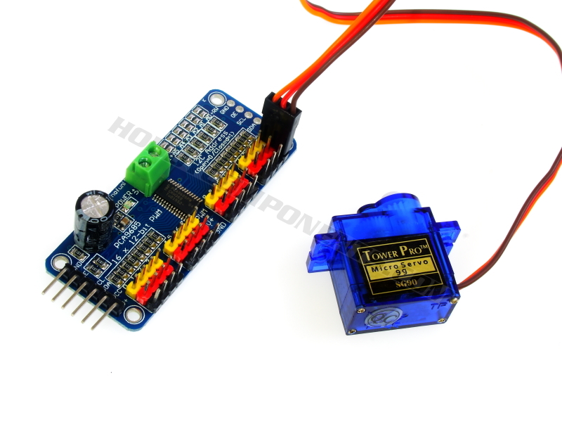

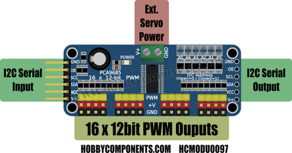
This module (HCMODU0097) is a breakout board for the NXP PCA9685 16 channel PWM controller. It features 16 fully programmable PWM outputs with a 12bit resolution giving a total of 4096 programmable steps with a duty cycle being adjustable from 0% to 100%. Additionally, the output frequency of all 16 channels can be programmed from 24Hz to 1526Hz. Intended for controlling the brightness of multiple LEDs, the programmability of its PWM outputs means that it can also be configured for producing PWM signals compatible with driving standard servos. In fact, this module has been designed with this purpose in mind with 16 sets of headers that allow for any servo with a standard header to be directly plugged into the module. A screw terminal block provides a means of powering the attached servos from an external 5V PSU and so the number of servos you can drive from your microcontroller and so is not limited by the microcontrollers own power supply. For Arduino users, with this module and our exclusive Arduino library (HCPCA9685) you can directly control up to 16 servos from your Arduino with only a few commands.
The module also includes an I2C header with 10K pullup resistors and so only requires two data pins (SDA & SCL) to control the module. Solderable pads on the module provide a means of changing the default I2C address (0x40) to one of 62 options, meaning more than one module can be connected to the same I2C bus.
A wide operating range of 2.3V to 5.5V allows the module to be powered from a range of power supplies and when powered from a 3.3V supply is safe to interface to a Raspberry Pi or 3.3V or any other non 5V tolerant microcontrollers.
PLEASE NOTE: The PWM output pins on this module are capable of sinking a maximum of 25mA or sourcing a maximum of 10mA. Do not attempt to drive high current devices such as motors, bulbs etc, directly from these pins as you will risk damaging the module. For servos, power is provided externally via the terminal header and only a small amount of current is drawn by the servo from each PWM pin.


Features:
• Product code: HCMODU0097
• Operating power supply voltage range of 2.3 V to 5.5 V with 5.5 V tolerant inputs
• 16 LED drivers. Each output programmable at: Off / On /ïµ ï®
• 1 MHz Fast-mode Plus compatible I2C-bus interface with 30 mA high drive capability on SDA output for driving high capacitive buses
• 4096-step (12-bit) linear programmable PWM output varying from fully
off (default) to maximum brightness
• Output frequency (all PWM output) typically varies from 24 Hz to 1526 Hzï®
• Sixteen totem pole outputs (sink 25 mA and source 10 mA at 5 V) with software
programmable open-drain LED outputs selection (default at totem pole). No input
function.
• 4 software programmable I2C-bus addresses (one LED All Call address and three LED
Sub Call addresses) allow groups of devices to be addressed at the same time in any
combination (for example, one register used for ‘All Call’ so that all the PCA9685s on
the I2C-bus can be addressed at the same time and the second register used for three
different addresses so that 1â„3 of all devices on the bus can be addressed at the same
time in a group). Software enable and disable for these I2C-bus address.
• 25 MHz typical internal oscillator requires no external components
• External 50 MHz (max.) clock input
• Internal power-on reset
• Noise filter on SDA/SCL inputs
• Edge rate control on outputs
• No output glitches on power-up
• Supports hot insertion
• Low standby current
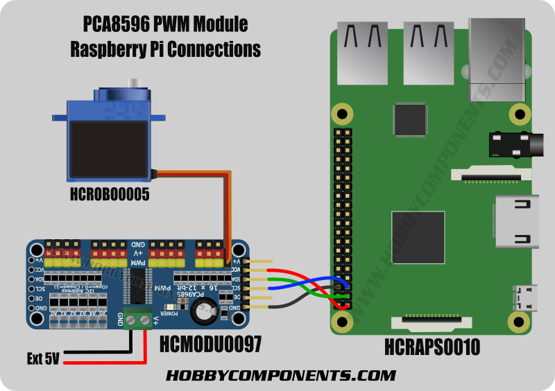
Raspberry Pi users:
For Raspberry Pi uses we have tested this module with the free Cayenne cloud based IoT software platform. Simply connect the module to your Raspberry Pi as shown below and use the Cayenne software platform to get remote analogue voltage readings without writing a single line of code.
You can create a free account simply by clicking our referral link below:

Arduino users:
To make using this module with your Arduino as easy as possible we have written an exclusive library (HCPCA9685). This library can be downloaded from the software section of our support forum here:
http://forum.hobbycomponents.com/viewto ... =58&t=2034
Example sketch using the HCPCA9685 library:
Code: Select all
/* FILE: HCPCA9685_Servo_Example
DATE: 10/06/16
VERSION: 0.1
AUTHOR: Andrew Davies
Sketch created by Hobby Components Ltd (HOBBYCOMPONENTS.COM)
10/06/16 version 0.1: Original version
This example demonstrates how to use the HCPCA9685 library together with the PCA9685
to control up to 16 servos. The sketch will initialise the library putting it into
'servo mode' and then will continuously sweep one servo connected to PWM output 0
back and forth. The example has been written particularly for the 16 Channel 12-bit
PWM Servo Motor Driver Module (HCMODU0097) available from hobbycomponents.com
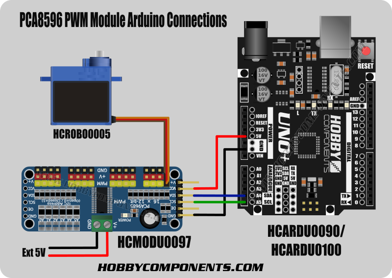
To use the module connect it to your Arduino as follows:
PCA9685...........Uno/Nano
GND...............GND
OE................N/A
SCL...............A5
SDA...............A4
VCC...............5V
External 5V Power for the servo(s) can be supplied by the V+ and GND input of the
screw terminal block.
PLEASE NOTE: Depending on your servo it is possible for this sketch to attempt
drive the servo beyond its end stops. If your servo is hitting its end stops then
you should adjust the the min and max values in this sketch.
You may copy, alter and reuse this code in any way you like, but please leave
reference to HobbyComponents.com in your comments if you redistribute this code.
This software may not be used directly for the purpose of selling products that
directly compete with Hobby Components Ltd's own range of products.
THIS SOFTWARE IS PROVIDED "AS IS". HOBBY COMPONENTS MAKES NO WARRANTIES, WHETHER
EXPRESS, IMPLIED OR STATUTORY, INCLUDING, BUT NOT LIMITED TO, IMPLIED WARRANTIES OF
MERCHANTABILITY AND FITNESS FOR A PARTICULAR PURPOSE, ACCURACY OR LACK OF NEGLIGENCE.
HOBBY COMPONENTS SHALL NOT, IN ANY CIRCUMSTANCES, BE LIABLE FOR ANY DAMAGES,
INCLUDING, BUT NOT LIMITED TO, SPECIAL, INCIDENTAL OR CONSEQUENTIAL DAMAGES FOR ANY
REASON WHATSOEVER.
*/
/* Include the HCPCA9685 library */
#include "HCPCA9685.h"
/* I2C slave address for the device/module. For the HCMODU0097 the default I2C address
is 0x40 */
#define I2CAdd 0x40
/* Create an instance of the library */
HCPCA9685 HCPCA9685(I2CAdd);
void setup()
{
/* Initialise the library and set it to 'servo mode' */
HCPCA9685.Init(SERVO_MODE);
/* Wake the device up */
HCPCA9685.Sleep(false);
}
void loop()
{
unsigned int Pos;
/* Sweep the servo back and forth from its minimum to maximum position.
If your servo is hitting its end stops then you should adjust the
values so that the servo can sweep though its full range without hitting
the end stops. You can adjust the min & max positions by altering
the trim values in the libraries HCPCA9685.h file*/
for(Pos = 10; Pos < 450; Pos++)
{
/* This function sets the servos position. It takes two parameters,
* the first is the servo to control, and the second is the servo
* position. */
HCPCA9685.Servo(0, Pos);
delay(10);
}
for(Pos = 450; Pos >= 10; Pos--)
{
HCPCA9685.Servo(0, Pos);
delay(10);
}
}
The HCPCA9685 Arduino compatible library required for the above sketch can be downloaded from the software section of our support forum here:
http://forum.hobbycomponents.com/viewto ... =58&t=2034
Disclaimer: The Cayenne platform is an external free service and is not provided by, or connected to, Hobby Components Ltd. It is therefore not being sold as part of product advertised on this page. As such we do not provide any guarantees or warranties with regards to this service. Issues or questions related to the Cayenne platform should be directed to Cayenne and not Hobby Components Ltd.
Libraries, example code, and diagrams are provided as an additional free courtesy by Hobby Components and are not sold as part of this product. We do no provide any guarantees or warranties as to their accuracy or fitness for purpose.
Descriptions and diagrams on this page are copyright Hobby Components Ltd and may not be reproduced without permission.