
Recommended supply voltage DC 10V-24V.
Toshiba TB6560A controller.
High speed opto-couplers.
Low voltage, over heating, and over current protection.
3A Maximum rated output current (3.5A peak).
Designed for 2/4 phase, 4 or 6 wire stepper motors with a maximum load current of 3A.
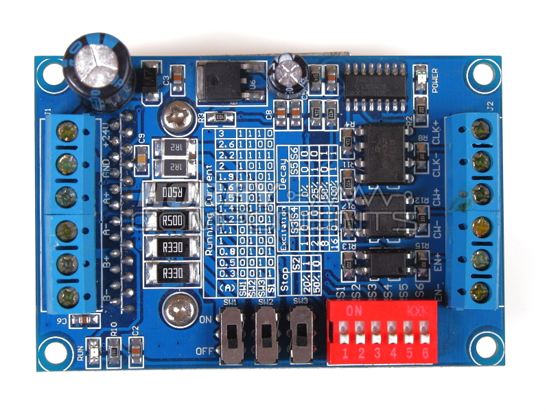
Adjustable load current protection.
Adjustable decay modes.
Excitation modes: 1/2, 1/8, 1/16 step.
Large passive heat-sink.
Dimensions: 50 x 75 x 35 mm
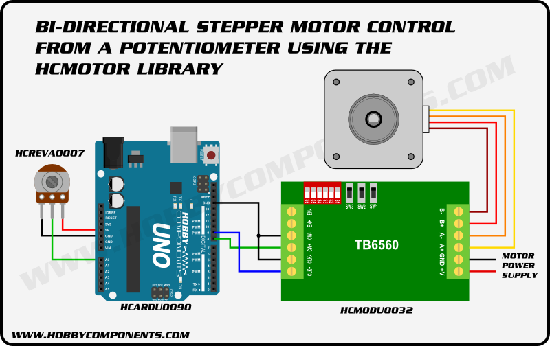
Example connections:
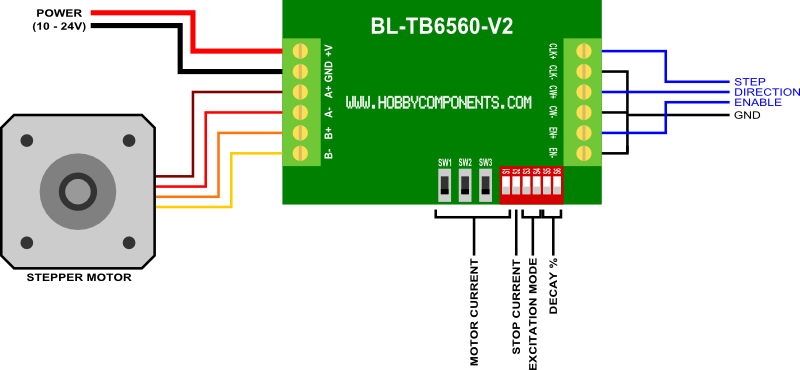
The EN, CW, and CLK inputs are opto-isolated. If you are connecting them directly to a microcontroller then we suggest grounding the EN-, CW-, and CLK- pins with your microcontroller as per the diagram above.
EN (Enable input): If connected as per above diagram, grounding EN+ input will enable the motor drive outputs. Providing a logic high will disable outputs to the motor.
CW (Direction input): If connected as per above diagram, grounding CW+ input will cause the motor to rotate anti-clockwise (counter-clockwise). Providing a logic high will cause the motor to rotate clockwise. The direction of rotation also depends upon the motor coil polarity.
CLK (Step input): Continually pulsing the CLK+ input will cause the motor to step in one direction. Depending on the excitation mode setting (via switches SW3 & 4) the motor will step once per 1 to 16 pulses of the CLK+ pin.
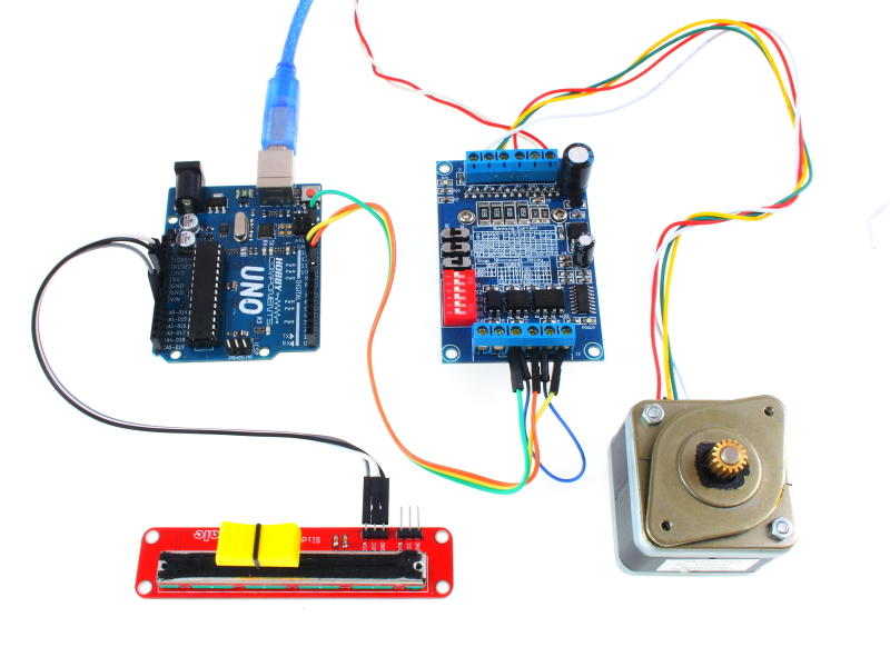
Arduino Example:
Code: Select all
/* Include the library */
#include "HCMotor.h"

/* Pins used to drive the motors */
#define DIR_PIN 8 //Connect to drive modules 'direction' input.
#define CLK_PIN 9 //Connect to drive modules 'step' or 'CLK' input.

/* Set the analogue pin the potentiometer will be connected to. */
#define POT_PIN A0

/* Set a dead area at the centre of the pot where it crosses from forward to reverse */
#define DEADZONE 20

/* The analogue pin will return values between 0 and 1024 so divide this up between
   forward and reverse */
#define POT_REV_MIN 0
#define POT_REV_MAX (512 - DEADZONE)
#define POT_FWD_MIN (512 + DEADZONE)
#define POT_FWD_MAX 1024


/* Create an instance of the library */
HCMotor HCMotor;


void setup()
{
  //Serial.begin(9600);
  /* Initialise the library */
  HCMotor.Init();

  /* Attach motor 0 to digital pins 8 & 9. The first parameter specifies the
     motor number, the second is the motor type, and the third and forth are the
     digital pins that will control the motor */
  HCMotor.attach(0, STEPPER, CLK_PIN, DIR_PIN);

  /* Set the number of steps to continuous so the the motor is always turning whilst
     not int he dead zone*/
  HCMotor.Steps(0,CONTINUOUS);
}


void loop()
{
  int Speed, Pot;

  /* Read the analogue pin to determine the position of the pot. */
  Pot = analogRead(POT_PIN);

  /* Is the pot in the reverse position ? */
  if (Pot >= POT_REV_MIN && Pot <= POT_REV_MAX)
  {
    HCMotor.Direction(0, REVERSE);
    Speed = map(Pot, POT_REV_MIN, POT_REV_MAX, 10, 1024);

  /* Is the pot in the forward position ? */
  }else if (Pot >= POT_FWD_MIN && Pot <= POT_FWD_MAX)
  {
    HCMotor.Direction(0, FORWARD);
    Speed = map(Pot, POT_FWD_MIN, POT_FWD_MAX, 1024, 10);

  /* Is the pot in the dead zone ? */
  }else
  {
    Speed = 0;
  }

  /* Set the duty cycle of the clock signal in 100uS increments */
  HCMotor.DutyCycle(0, Speed);

}
The HCMotor Arduino library and the above example can be found in the software section of our support forum here: http://forum.hobbycomponents.com/viewto ... =58&t=1870
