

This module contains a strip of 8 individually controllable RGB LEDs arranged in a serial (daisy-chain) configuration. Each LEDs red, green, and blue, elements can be individually set to one of 256 intensity settings allowing a over 16 million colour variations. The module also has power and data connection at both ends so that multiple modes can be connected together whilst still only requiring one digital pin to drive them.
What's more, to make controlling these LED's from an Arduino as simple as possible we have written our own exclusive library what will handle all the complicated bits. We also decided to go one better an allow you to stack multiple the strips in columns to create a full colour message display! See our forum or blog for more information on this library and requirements.

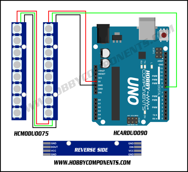
Image showing 8 modules in series. Note: When powering multiple modules at full brightness an external 5V supply may be required.

Model number: HCMODU0075
Supply voltage: 4 to 7V (5V recommended)
LEDs per strip: 8
Max module current: 100mA (approx)
Module length: 54.5mm
Module width: 10.5mm

Input header:
GND.....0V
DIN......Data in
VCC.....Supply input
GND.....0V
Output header:
GND.....0V
DOUT...Data out
VCC.....Supply input
GND.....0V

Code: Select all
/* FILE:    HCWS2812_Cylon_Example
   DATE:    26/03/15
   VERSION: 0.1
   AUTHOR:  Andrew Davies

11/03/15 version 0.1: Original version

This is an example of how to use the HCMAX7219 library to control one or more
RGB LEDS. The example will set each LED to a random colour.

To use this example connect one or more LEDs in series (Dout --> Din) and connect
the first LED's Din pin to digital pin 8 of your Arduino.

By default the library is set to control 100 LEDs. You can change this by editing the
following line in the MCMAX7219.h header file:

#define NUMBEROFLEDS 200 <--- Change this number to match the number of LEDS connected

You can download the library from the software section of our support forum here:
http://forum.hobbycomponents.com/viewforum.php?f=58

Or from Github here:
https://github.com/HobbyComponents/HCWS2812


You may copy, alter and reuse this code in any way you like, but please leave
reference to HobbyComponents.com in your comments if you redistribute this code.
This software may not be used directly for the purpose of selling products that
directly compete with Hobby Components Ltd's own range of products.

THIS SOFTWARE IS PROVIDED "AS IS". HOBBY COMPONENTS MAKES NO WARRANTIES, WHETHER
EXPRESS, IMPLIED OR STATUTORY, INCLUDING, BUT NOT LIMITED TO, IMPLIED WARRANTIES OF
MERCHANTABILITY AND FITNESS FOR A PARTICULAR PURPOSE, ACCURACY OR LACK OF NEGLIGENCE.
HOBBY COMPONENTS SHALL NOT, IN ANY CIRCUMSTANCES, BE LIABLE FOR ANY DAMAGES,
INCLUDING, BUT NOT LIMITED TO, SPECIAL, INCIDENTAL OR CONSEQUENTIAL DAMAGES FOR ANY
REASON WHATSOEVER.
*/

/* Include the HCWS2812 library */
#include "HCWS2812.h"

/* Create an instance of the library */
HCWS2812 HCWS2812;

void setup()
{
  /* Set the R,G,B background colours to zero */
  HCWS2812.SetBG(0, 0, 0);
  /* Clear the output buffer */
  HCWS2812.ClearBuffer();
}


/* Main program */
void loop()
{
  int index;

  /* Step forward through each LED */
  for(index = 0; index < NUMBEROFLEDS; index++)
  {
    HCWS2812.ClearBuffer();
    RGBBuffer[RED][index] = 255;
    HCWS2812.Refresh();
    delay(100);
  }

  /* Step backward through each LED */
  for(index = NUMBEROFLEDS; index; index--)
  {
    HCWS2812.ClearBuffer();
    RGBBuffer[RED][index - 1] = 255;
    HCWS2812.Refresh();
    delay(100);
  }
}
Code: Select all
/* FILE:    HCWS2812_Random_Example
   DATE:    26/03/15
   VERSION: 0.1
   AUTHOR:  Andrew Davies

11/03/15 version 0.1: Original version

This is an example of how to use the HCMAX7219 library to control one or more
RGB LEDS. The example will set each LED to a random colour.

To use this example connect one or more LEDs in series (Dout --> Din) and connect
the first LED's Din pin to digital pin 8 of your Arduino.

By default the library is set to control 100 LEDs. You can change this by editing the
following line in the MCMAX7219.h header file:

#define NUMBEROFLEDS 200 <--- Change this number to match the number of LEDS connected

You can download the library from the software section of our support forum here:
http://forum.hobbycomponents.com/viewforum.php?f=58

Or from Github here:
https://github.com/HobbyComponents/HCWS2812

You may copy, alter and reuse this code in any way you like, but please leave
reference to HobbyComponents.com in your comments if you redistribute this code.
This software may not be used directly for the purpose of selling products that
directly compete with Hobby Components Ltd's own range of products.

THIS SOFTWARE IS PROVIDED "AS IS". HOBBY COMPONENTS MAKES NO WARRANTIES, WHETHER
EXPRESS, IMPLIED OR STATUTORY, INCLUDING, BUT NOT LIMITED TO, IMPLIED WARRANTIES OF
MERCHANTABILITY AND FITNESS FOR A PARTICULAR PURPOSE, ACCURACY OR LACK OF NEGLIGENCE.
HOBBY COMPONENTS SHALL NOT, IN ANY CIRCUMSTANCES, BE LIABLE FOR ANY DAMAGES,
INCLUDING, BUT NOT LIMITED TO, SPECIAL, INCIDENTAL OR CONSEQUENTIAL DAMAGES FOR ANY
REASON WHATSOEVER.
*/

/* Include the HCWS2812 library */
#include "HCWS2812.h"

/* Create an instance of the library */
HCWS2812 HCWS2812;

void setup()
{
  /* Set the R,G,B background colours to zero */
  HCWS2812.SetBG(0, 0, 0);
  /* Clear the output buffer */
  HCWS2812.ClearBuffer();
}


void loop()
{
  int index;

  /* Fill the output buffer with random colours */
  for(index = 0; index < NUMBEROFLEDS; index++)
  {
    RGBBuffer[RED][index] = random(0,255);
    RGBBuffer[GREEN][index] = random(0,255);
    RGBBuffer[BLUE][index] = random(0,255);
  }

  /* Send the output buffer to the LEDs */
  HCWS2812.Refresh();

  /* Wait a moment before doing it again */
  delay(100);
}
Code: Select all
/* FILE:    HCWS2812_Message_Display_Example
   DATE:    26/03/15
   VERSION: 0.1
   AUTHOR:  Andrew Davies

11/03/15 version 0.1: Original version

This is an example of how to use the HCMAX7219 library to create a message display.
To use this example you will need to connect the LEDs in series (Dout --> Din) and
arrange them in columns of 8 to create your LED array. Connect the Din of the first
LED to digital pin  of your Arduino.

You can create as many columns of 8 LEDs as you like but you will need to edit the
following line in the HCWS2812.h header file:

#define NUMBEROFLEDS 200 <--- Change this number to match the number of LEDS connected

This value must be an multiple of 8 otherwise the print functions will not work

You can download the library from the software section of our support forum here:
http://forum.hobbycomponents.com/viewforum.php?f=58

Or from Github here:
https://github.com/HobbyComponents/HCWS2812


You may copy, alter and reuse this code in any way you like, but please leave
reference to HobbyComponents.com in your comments if you redistribute this code.
This software may not be used directly for the purpose of selling products that
directly compete with Hobby Components Ltd's own range of products.

THIS SOFTWARE IS PROVIDED "AS IS". HOBBY COMPONENTS MAKES NO WARRANTIES, WHETHER
EXPRESS, IMPLIED OR STATUTORY, INCLUDING, BUT NOT LIMITED TO, IMPLIED WARRANTIES OF
MERCHANTABILITY AND FITNESS FOR A PARTICULAR PURPOSE, ACCURACY OR LACK OF NEGLIGENCE.
HOBBY COMPONENTS SHALL NOT, IN ANY CIRCUMSTANCES, BE LIABLE FOR ANY DAMAGES,
INCLUDING, BUT NOT LIMITED TO, SPECIAL, INCIDENTAL OR CONSEQUENTIAL DAMAGES FOR ANY
REASON WHATSOEVER.
*/

/* Include the HCWS2812 library */
#include "HCWS2812.h"

/* Create an instance of the library */
HCWS2812 HCWS2812;

void setup()
{
  Serial.begin(9600);

  /* Set the fonts R G B colour to white */
  HCWS2812.SetFontFG(100, 100, 100);
  /* Set the fonts R G B background colour to light red */
  HCWS2812.SetBG(20, 0, 0);
}

/* Main program */
void loop()
{
  byte index;

  /* Scroll some text with random background colours */
  for(index = 0; index < 160; index++)
  {
    /* Clear the output buffer */
    HCWS2812.ClearBuffer();
    /* Change the fonts background colour every 16 steps */
    if (index % 16 == 0)
      HCWS2812.SetFontBG(random(0,20), random(0,20), random(0,20));

    /* Print some text to the output buffer */
    HCWS2812.print("HOBBY COMPONENTS", index);

    /* Send the contents of the output buffer to the LEDs */
    HCWS2812.Refresh();

    /* Wait a little before moving the text to the next position */
    delay(80);
  }

  HCWS2812.ClearBuffer();
  /* Set the fonts background colour to light green */
  HCWS2812.SetFontBG(0, 20, 0);

  /* Scroll an integer number */
  for(index = 0; index < 64; index++)
  {
    HCWS2812.ClearBuffer();
    HCWS2812.print(-1234, index);
    HCWS2812.Refresh();
    delay(80);
  }


  HCWS2812.ClearBuffer();
  /* Set the fonts background colour to light green */
  HCWS2812.SetFontBG(0, 20, 0);

  /* Scroll an integer number with a decimal point
     (notice a leading zero is added) */
  for(index = 0; index < 80; index++)
  {
    HCWS2812.ClearBuffer();
    HCWS2812.print(-1234, 4, index);
    HCWS2812.Refresh();
    delay(80);
  }
}

The library files can be downloaded from github here:
https://github.com/HobbyComponents/HCWS2812
Or directly from this forum:
http://forum.hobbycomponents.com/viewto ... =58&t=1799
Datasheet: