Description:
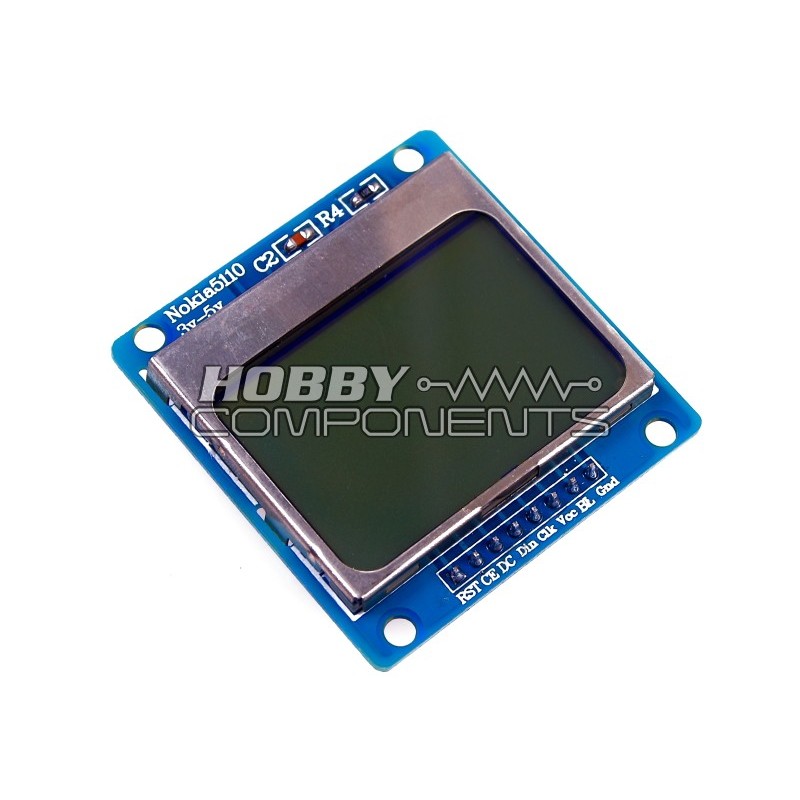
The Nokia 5110 Graphic LCD module is a low cost LCD module based on the PCD8544 controller. It has a monochrome display resolution of 84x48 pixels with an integrated blue LED backlight. Interfacing to the display only requires 5 DIO lines which although the controller chip is not 5V tolerant, the display itself is. If you intend to use this module with an Arduino, we have an exclusive library available.
Specifications:
Controller: PCD8544
Supply: 2.7V to 3.3V
Interface levels: 2.7V to 5V
Backlight Colour: Blue
Backlight supply: 3.3V Max
Module size: W 43.6mm x H 43.1mm
Working current: < 200uA (Backlight off)
Example Arduino Sketch:
Code: Select all
/* FILE:    HC5110_Example
   DATE:    07/09/13
   VERSION: 0.1
   AUTHOR:  Andrew Davies

This is an example of how to use the functions within the HC5110 library written
for the Nokia 5110 LCD module (HCMODU0037). This example will display example
text, a graphic, and formatted decimal number.

You can specify which DIO pins on your Arduino connect to the module but if left
unchanged you will need to make the following connections:

MODULE   UNO
RST      D3
CE       D4
DC       D5
DIN      D6
CLK      D7
VCC      3.3V
BL       3.3V
GND      GND


WARNING: Do not power the module or its backlight via the Arduino's 5V pin. This
will distroy the module. Although the module is 3.3V only, the digital pins are
5V tollarant, so it is safe to connect them directly to 5V DIO pins


You may copy, alter and reuse this code in any way you like, but please leave
reference to HobbyComponents.com in your comments if you redistribute this code.
This software may not be used directly for the purpose of selling products that
directly compete with Hobby Components Ltd's own range of products.

THIS SOFTWARE IS PROVIDED "AS IS". HOBBY COMPONENTS MAKES NO WARRANTIES, WHETHER
EXPRESS, IMPLIED OR STATUTORY, INCLUDING, BUT NOT LIMITED TO, IMPLIED WARRANTIES OF
MERCHANTABILITY AND FITNESS FOR A PARTICULAR PURPOSE, ACCURACY OR LACK OF NEGLIGENCE.
HOBBY COMPONENTS SHALL NOT, IN ANY CIRCUMSTANCES, BE LIABLE FOR ANY DAMAGES,
INCLUDING, BUT NOT LIMITED TO, SPECIAL, INCIDENTAL OR CONSEQUENTIAL DAMAGES FOR ANY
REASON WHATSOEVER.
*/

/* Example bitmap */
const byte Tiny_Logo_Resistor [] = {
0x80, 0xC0, 0x60, 0x60, 0xE0, 0xC0, 0x80, 0x80, 0x80, 0x80, 0x80, 0x80, 0x80, 0x80, 0x80, 0x00,
0x00, 0x00, 0x00, 0x00, 0xC0, 0x70, 0x1C, 0x0E, 0x3C, 0xF0, 0xC0, 0x00, 0x00, 0x00, 0x00, 0x00,
0x80, 0xE0, 0x38, 0x0E, 0x1E, 0x78, 0xE0, 0x00, 0x00, 0x00, 0x00, 0x00, 0x00, 0xE0, 0x78, 0x1E,
0x0E, 0x38, 0xE0, 0x80, 0x00, 0x00, 0x00, 0x00, 0x00, 0xC0, 0xF0, 0x3C, 0x0E, 0x1C, 0x70, 0xC0,
0x00, 0x00, 0x00, 0x00, 0x00, 0x80, 0x80, 0x80, 0x80, 0x80, 0x80, 0x80, 0x80, 0x80, 0xC0, 0xE0,
0x60, 0x60, 0xC0, 0x80, 0x01, 0x03, 0x06, 0x06, 0x07, 0x03, 0x01, 0x01, 0x01, 0x01, 0x01, 0x01,
0x01, 0x01, 0x07, 0x1E, 0x78, 0x70, 0x1C, 0x07, 0x01, 0x00, 0x00, 0x00, 0x00, 0x00, 0x03, 0x0F,
0x3C, 0x70, 0x38, 0x0E, 0x03, 0x00, 0x00, 0x00, 0x00, 0x00, 0x01, 0x07, 0x1C, 0x70, 0x70, 0x1C,
0x07, 0x01, 0x00, 0x00, 0x00, 0x00, 0x00, 0x03, 0x0E, 0x38, 0x70, 0x3C, 0x0F, 0x03, 0x00, 0x00,
0x00, 0x00, 0x00, 0x01, 0x07, 0x1C, 0x70, 0x78, 0x1E, 0x07, 0x01, 0x01, 0x01, 0x01, 0x01, 0x01,
0x01, 0x01, 0x03, 0x07, 0x06, 0x06, 0x03, 0x01,
};

/* Include the HC5110 library header */
#include <HC5110.h>

/* Create an instance of HC5110 library and define the DIO pins
   used (RST,CD,DC,DIN,CLK) */
HC5110 HC5110(3,4,5,6,7);

/* Set the displays contrast. */
void setup()
{
  HC5110.Contrast(0xB0);
}

/* Main program */
void loop()
{
  /* Display some text */
  HC5110.Clear();
  HC5110.Home();
  HC5110.Cursor(20, 0);
  HC5110.Print("Hobby");
  HC5110.Cursor(0, 1);
  HC5110.Print("Components");

  /* Display a graphic */
  HC5110.Cursor(0, 3);
  HC5110.Bitmap(84, 2, Tiny_Logo_Resistor);

  /* Wait a little then clear the screen */
  delay(2000);
  HC5110.Clear();

  /* Display some example numbers */
  HC5110.Print(12345678);
  HC5110.Cursor(0, 1);
  HC5110.Print(-12345678);
  HC5110.Cursor(0, 2);
  HC5110.Print(12345678,2);
  delay(2000);
}
The Arduino library can be found within the software section of this forum here
