Order yours here
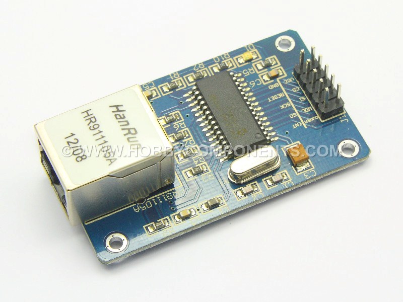
ENC28J60 Ethernet Module utilizes the new Microchip ENC28J60 Stand-Alone Ethernet Controller IC featuring a host of features to handle most of the network protocol requirements. This Ethernet LAN module connects directly to most microcontrollers.
Features
Ethernet LAN Module for Arduino/AVR/LPC/STM3
ENC28J60 Ethernet chips
Can be easily mounted with the MCU
Network Interface: HR911105A
Supply Voltage: 3.3 V (5V Tolerant DIO)
25Mhz crystal oscillator
Size (L x W x H): Approx. 2.3 x 1.3 x 0.7 inch / 58 x 34 x 17 mm
- PINOUT
1.....CLK OUT
2.....INT
3.....WOL
4.....SO
5.....SI
6.....SCK
7.....CS
8.....RES
9.....+3.3V
10....GND
Edit:
This post has now been updated to use the newer and currently maintained Arduino etherCard libraries. A new sketch had also been added to provide an example of how to use this new library with your ethernet module. If you are using V1.0 or above of the Arduino software environment, we recommend using this new library and sketch.
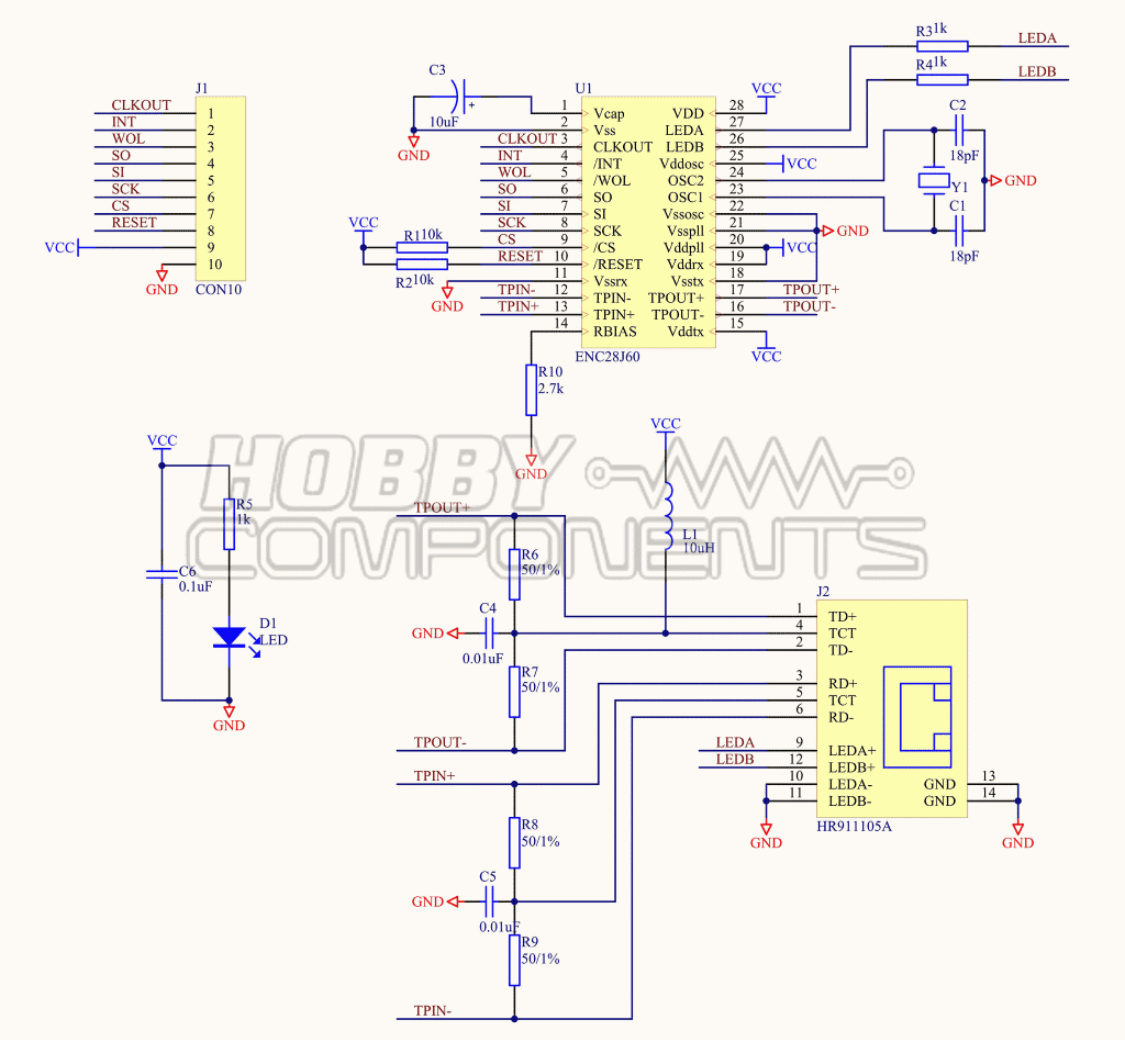
Schematic:
Arduino Libraries:
etherCard library Out of date pre V1.0 Arduino environment library: Example Arduino sketch for etherCard library:
Code: Select all
/* FILE:    ENC28J60_Ethernet_Module_Example
   DATE:    10/06/13
   VERSION: 0.1

This is an example of how to use the Hobby Components ENC28J60 Ethernet
module (HCARDU0028).

To use this sketch you will need to download and install the EthernetCard library
available at the following location:

https://github.com/jcw/ethercard

Alternatively, a known working snapshot can be downloaded from the microduino section
of our support forum:

http://forum.hobbycomponents.com/

This example program will serve a basic webpage at the ip address specified below.
As an example of content, the webpage contains the current status of the analogue input
pins.

CONNECTIONS:

ETHERNET MODULE       UNO/NANO
PIN 1  (CLK OUT)      N/A
PIN 2  (INT)          N/A
PIN 3  (WOL)          N/A
PIN 4  (SO)           DIO 12
PIN 5  (SI)           DIO 11
PIN 6  (SCK)          DIO 13
PIN 7  (CS)           DIO 8
PIN 8  (RES)          N/A
PIN 9  (VCC)          +3.3V
PIN 10 (GND)          GND


REVISIONS:

V0.1 Initial version


You may copy, alter and reuse this code in any way you like, but please leave
reference to HobbyComponents.com in your comments if you redistribute this code.
This software may not be used directly for the purpose of selling products that
directly compete with Hobby Components Ltd's own range of products.

THIS SOFTWARE IS PROVIDED "AS IS". HOBBY COMPONENTS MAKES NO WARRANTIES, WHETHER
EXPRESS, IMPLIED OR STATUTORY, INCLUDING, BUT NOT LIMITED TO, IMPLIED WARRANTIES OF
MERCHANTABILITY AND FITNESS FOR A PARTICULAR PURPOSE, ACCURACY OR LACK OF NEGLIGENCE.
HOBBY COMPONENTS SHALL NOT, IN ANY CIRCUMSTANCES, BE LIABLE FOR ANY DAMAGES,
INCLUDING, BUT NOT LIMITED TO, SPECIAL, INCIDENTAL OR CONSEQUENTIAL DAMAGES FOR ANY
REASON WHATSOEVER.

*/


/* Include the EtherCard library */
#include <EtherCard.h>

/* The IP address of the module. Make sure this matches the IP
   address range of your network and that it is not in use by any other
   device on it */
static uint8_t IPaddress[] = { 192,168,1,55 };

/* The gateway IP address of your router */
static uint8_t GatewayIP[] = { 192,168,1,1 };

/* MAC address of the ethernet shield. If you are using this on your
own network then the MAC address below will be fine, but remember if
you use more than one module on your network they will need to be assigned
unique MAC addresses */
static uint8_t MACAddress[6] = {0x54, 0x55, 0x58, 0x10, 0x00, 0x24};

/* Create a buffer for send and receive data */
byte Ethernet::buffer[500];
BufferFiller bfill;


void setup()
{
  /* Initialise the ethernet interface */
  if (ether.begin(sizeof Ethernet::buffer, MACAddress) == 0)
  {
    /* If it failed to initialise then do nothing */
    while(1);
  }
  /* Else set up a fixed IP address */
  ether.staticSetup(IPaddress, GatewayIP);
}


/* Main program */
void loop()
{
  /* Get length of recived packet */
  word PacketLength = ether.packetReceive();

  /* Has a valid packet been received? If so, then send the web page */
  if (ether.packetLoop(PacketLength))
    ether.httpServerReply(ExampleContenet());
}

/* An example web page which returns the state of the analogue inputs */
static word ExampleContenet()
{
  bfill = ether.tcpOffset();
  bfill.emit_p(PSTR(
    "HTTP/1.0 200 OK\r\n"
    "Content-Type: text/html\r\n"
    /*"Pragma: no-cache\r\n"*/
    "\r\n"
    "<meta http-equiv='refresh' content='1'/>"
    "<big><span style=\"font-weight: bold;\">www.hobbycomponents.com"
    "<br>Microduino Ethernet Example:</span></big><br>"
    "*******************<br>"
    "Analogue Pin A0.....$D<BR>"
    "Analogue Pin A1.....$D<BR>"
    "Analogue Pin A2.....$D<BR>"
    "Analogue Pin A3.....$D<BR>"
    "Analogue Pin A4.....$D<BR>"
    "Analogue Pin A5.....$D<BR>"
    "*******************<br>"),
    /* Read the analogue inputs */
    analogRead(0),analogRead(1),analogRead(2),analogRead(3),analogRead(4),analogRead(5));
  /* Return the current buffer position */
  return bfill.position();
}
Example Arduino sketch for older pre V1.0 library.
Code: Select all
/* FILE:    ARD_Ethernet_Module_HCARDU0028_Example.pde
   DATE:    28/07/12
   VERSION: 0.1

This is an example of how to use the HobbyComponents Arduino module shield
(HCARDU0028). For this example to work you will need to download the appropriate
libraries available at:
http://forum.hobbycomponents.com/viewtopic.php?f=25&t=6

Unzip the libraries and copy them to your Arduino libraries folder.

This program will serve a basic webpage at the ip address specified below which will
allow you change the state of 4 relays. This program is intended to work with arduino
relay modules such as the HobbyComponents 4 channel relay module (HCARDU0025).


CONNECTIONS:

ETHERNET MODULE       ARDUINO BOARD
PIN 1  (CLK OUT)      N/A
PIN 2  (INT)          N/A
PIN 3  (WOL)          N/A
PIN 4  (SO)           DIO 12
PIN 5  (SI)           DIO 11
PIN 6  (SCK)          DIO 13
PIN 7  (CS)           DIO 10
PIN 8  (RES)          N/A
PIN 9  (VCC)          +3.3V
PIN 10 (GND)          GND


You may copy, alter and reuse this code in any way you like but please leave
reference to HobbyComponents.com in your comments if you redistribute this code. */

/* Include both ethernet libraries */
#include "etherShield.h"
#include "ETHER_28J60.h"

#define RELAY1_DIO 2  /* DIO pin used to drive relay 1 */
#define RELAY2_DIO 3  /* DIO pin used to drive relay 2 */
#define RELAY3_DIO 4  /* DIO pin used to drive relay 3 */
#define RELAY4_DIO 5  /* DIO pin used to drive relay 4 */

#define RELAY1_MASK 0 /* Bit mask for storing state of relay 1 */
#define RELAY2_MASK 1 /* Bit mask for storing state of relay 2 */
#define RELAY3_MASK 2 /* Bit mask for storing state of relay 3 */
#define RELAY4_MASK 3 /* Bit mask for storing state of relay 4 */


/* Used to store the current state of the relays */
int RelayState = 0;

/* MAC address of the ethernet shield. If you are using this on your
own network then the MAC address below will be fine, but remember if
you use more than one shield on your network they will need to be assigned
unique MAC addresses */
static uint8_t mac[6] = {0x54, 0x55, 0x58, 0x10, 0x00, 0x24};


/* The IP address of the shield. Make sure this matches the IP
   address range of your network and is not in use by any other
   device on it */

static uint8_t ip[4] = {192, 168, 1, 55};

/* The port number the shield will respond to. Use port 80
   for standard HTTP requests */

static uint16_t port = 80;

ETHER_28J60 e;


/* Initialise the ethernet interface and DIO pins */
void setup()
{
  e.setup(mac, ip, port);
  pinMode(RELAY1_DIO, OUTPUT);
  pinMode(RELAY2_DIO, OUTPUT);
  pinMode(RELAY3_DIO, OUTPUT);
  pinMode(RELAY4_DIO, OUTPUT);
}

/* Main program */
void loop()
{
  char* EthernetData;

  /* Has a page request been made? */
  if (EthernetData = e.serviceRequest())
  {

    /* Has the page link for relay 1 been pressed? */
    if (strcmp(EthernetData, "?relay=1") == 0)
    {
      /* If so then change the state of relay 1 */
      if (bitRead(RelayState, RELAY1_MASK))
      {
        bitClear(RelayState, RELAY1_MASK);
        digitalWrite(RELAY1_DIO, LOW);
      }else
      {
        bitSet(RelayState, RELAY1_MASK);
        digitalWrite(RELAY1_DIO, HIGH);
      }
    }

    /* Has the page link for relay 2 been pressed? */
    if (strcmp(EthernetData, "?relay=2") == 0)
    {
      /* If so then change the state of relay 2 */
      if (bitRead(RelayState, RELAY2_MASK))
      {
        bitClear(RelayState, RELAY2_MASK);
        digitalWrite(RELAY2_DIO, LOW);
      }else
      {
        bitSet(RelayState, RELAY2_MASK);
        digitalWrite(RELAY2_DIO, HIGH);
      }
    }

    /* Has the page link for relay 3 been pressed? */
    if (strcmp(EthernetData, "?relay=3") == 0)
    {
      /* If so then change the state of relay 3 */
      if (bitRead(RelayState, RELAY3_MASK))
      {
        bitClear(RelayState, RELAY3_MASK);
        digitalWrite(RELAY3_DIO, LOW);
      }else
      {
        bitSet(RelayState, RELAY3_MASK);
        digitalWrite(RELAY3_DIO, HIGH);
      }
    }

    /* Has the page link for relay 4 been pressed? */
    if (strcmp(EthernetData, "?relay=4") == 0)
    {
      /* If so then change the state of relay 4 */
      if (bitRead(RelayState, RELAY4_MASK))
      {
        bitClear(RelayState, RELAY4_MASK);
        digitalWrite(RELAY4_DIO, LOW);
      }else
      {
        bitSet(RelayState, RELAY4_MASK);
        digitalWrite(RELAY4_DIO, HIGH);
      }
    }

    /* Generate a new page with the current states of the relays */
    iUpdateRelays(RelayState);

    /* And send it back to the IP address that made the request */
    e.respond();
  }
}


/* This funtion generates a web page that shows the current state of
   the 4 relays and creates links to allow their states to be toggled.
   It requires a register of type int that holds the current state of
   the relays to be passed to it */

void iUpdateRelays(int RelayState)
{
    e.print("<H1>Web Remote</H1>");

    if (bitRead(RelayState, RELAY1_MASK))
    {
      e.print("RELAY 1: <A HREF='?relay=1'>ON</A><br>");
    }else
    {
      e.print("RELAY 1: <A HREF='?relay=1'>OFF</A><br>");
    }

    if (bitRead(RelayState, RELAY2_MASK))
    {
      e.print("RELAY 2: <A HREF='?relay=2'>ON</A><br>");
    }else
    {
      e.print("RELAY 2: <A HREF='?relay=2'>OFF</A><br>");
    }

    if (bitRead(RelayState, RELAY3_MASK))
    {
      e.print("RELAY 3: <A HREF='?relay=3'>ON</A><br>");
    }else
    {
      e.print("RELAY 3: <A HREF='?relay=3'>OFF</A><br>");
    }

    if (bitRead(RelayState, RELAY4_MASK))
    {
      e.print("RELAY 4: <A HREF='?relay=4'>ON</A><br>");
    }else
    {
      e.print("RELAY 4: <A HREF='?relay=4'>OFF</A><br>");
    }

}
