
The GP2Y1010AU/GP2Y1014AU (HCSENS0024) from Sharp is an optical air quality sensor, designed to sense dust particles. An infrared emitting diode (IRED) and a phototransistor are diagonally arranged into this device, which allows it to detect the reflected light of dust in air. It is very effective in detecting very fine particles like the cigarette smoke.
The sensor has a very low consumption current of only 20mA (MAX) (11mA Typical) whilst the sensor is taking a measurement. The output of the sensor is an analogue voltage proportional to the measured dust density, with a sensitivity of 0.5V/0.1mg/m3.
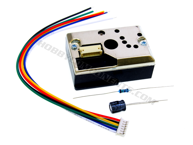
This sensor comes complete with a connection cable (connector already attached), a 150 Ohm current limiting resistor for use with the IR LED, and a 220uF 16V capacitor. Please see diagram for how to use these components.

Overall Dimensions: 46mm x 33mm x 18mm
Product code: HCSENS0024
Please note: This sensor has been calibrated by the factory. Adjusting the sensitivity potentiometer situated on the back of the module will cause the module to give inaccurate readings.
A suitable capacitor and resistor are supplied with this kit. Do not omit these components as it will cause damage and/or inaccurate reading from the sensor
Pinout:
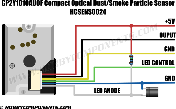
GP2Y1010AU
Pin 1 (WHT)......IR LED power (5V via supplied 150 Ohm resistor)
Pin 2 (BLU).......GND
Pin 3 (GRN).......IR LED control (HIGH = IR LED off, LOW = IR LED on)
Pin 4 (YEL)........GND (connected to case)
Pin 5 (BLK)........Sensors analogue output
Pin 6 (RED).......5V power
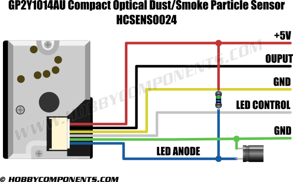
GP2Y1014AU
Pin 1 (BLU).......IR LED power (5V via supplied 150 Ohm resistor)
Pin 2 (GRN).......GND
Pin 3 (WHT).......IR LED control (HIGH = IR LED off, LOW = IR LED on)
Pin 4 (YEL).......GND (connected to case)
Pin 5 (BLK).......Sensors analogue output
Pin 6 (RED).......5V power
Example sketch:
Code: Select all
/* FILE:    GP2Y1010AU0F_Dust_Sensor_Example
   DATE:    24/08/17
   VERSION: 0.2
   AUTHOR:  Andrew Davies

   15/08/16: V0.1 initial version.
   24/10/17: V0.2 reduce ADC sampling delay from 320us to 280us

This example Arduino sketch will read the analogue voltage from the dust senors output
pin and convert it into a mg/m^3 value. To keep the sketch simple the result is based
on an approximation of the linear part of the output v dust density graph in the
datasheet.

You will need to connect the sensor to your Arduino as follows:

GP2Y1010AU............Arduino
Pin 1 (WHT).......5V via 150 Ohm resistor
Pin 2 (GRN).......GND
Pin 3 (WHT).......D2
Pin 4 (YEL).......GND
Pin 5 (BLK).......A0
Pin 6 (RED).......5V

GP2Y1014AU............Arduino
Pin 1 (BLU).......5V via 150 Ohm resistor
Pin 2 (GRN).......GND
Pin 3 (WHT).......D2
Pin 4 (YEL).......GND
Pin 5 (BLK).......A0
Pin 6 (RED).......5V

Additionally a 220uF capacitor should be connected across the sensors Pin 5 and GND

You may copy, alter and reuse this code in any way you like, but please leave
reference to HobbyComponents.com in your comments if you redistribute this code.
This software may not be used directly for the purpose of selling products that
directly compete with Hobby Components Ltd's own range of products.

THIS SOFTWARE IS PROVIDED "AS IS". HOBBY COMPONENTS MAKES NO WARRANTIES, WHETHER
EXPRESS, IMPLIED OR STATUTORY, INCLUDING, BUT NOT LIMITED TO, IMPLIED WARRANTIES OF
MERCHANTABILITY AND FITNESS FOR A PARTICULAR PURPOSE, ACCURACY OR LACK OF NEGLIGENCE.
HOBBY COMPONENTS SHALL NOT, IN ANY CIRCUMSTANCES, BE LIABLE FOR ANY DAMAGES,
INCLUDING, BUT NOT LIMITED TO, SPECIAL, INCIDENTAL OR CONSEQUENTIAL DAMAGES FOR ANY
REASON WHATSOEVER. */


/* The following values are a rough approximation taken from the datasheet graph.
 * To simplify the sketch, calculations are based on the liner operating range
 * of the sensor. */

/* Sensor voltage at 0mg/m^3 */
#define VOLTAGE_AT_0_MG_M3    0.6
/* Sensor voltage at 0.5mg/m^3 */
#define VOLTAGE_AT_0_5_MG_M3    3.6
/* As the ADC and the sensor outputs are both linear we can simply scale the output
*  voltage of the sensor to convert from volts to mg/m^3. */
#define SCALLING_FACTOR 0.5 / (VOLTAGE_AT_0_5_MG_M3 - VOLTAGE_AT_0_MG_M3)

/* Control pin for sensors IR-LED */
#define LED_PIN 2
/* Sensors output pin */
#define SENSOR_PIN A0

void setup()
{
  /* Set up serial interface and configure the LED pin */
  Serial.begin(9600);
  pinMode(LED_PIN, OUTPUT);
  digitalWrite(LED_PIN, HIGH);
}

void loop()
{
  int Result;
  float SensorVoltage;
  float DustDensity;

  /* Turn the sensors IR LED on for 320us */
  digitalWrite(LED_PIN, LOW);
  delayMicroseconds(280);

  /* Read the sensors analogue output */
  Result = analogRead(SENSOR_PIN);

  /* Turn the IR LED off */
  digitalWrite(LED_PIN, HIGH);

  /* Show the result in volts */
  Serial.print("Sensor voltage: ");
  SensorVoltage = Result * (5.00 / 1024);
  Serial.println(SensorVoltage);

  /* Show the result in mg/m^3 */
  DustDensity =  (SensorVoltage - VOLTAGE_AT_0_MG_M3) * SCALLING_FACTOR;
  Serial.print("Dust density: ");
  Serial.println(DustDensity);
  Serial.println();
  delay(1000);
}
Datasheet:
Disclaimer: Libraries, example code, and diagrams are provided as an additional free service by Hobby Components and are not sold as part of this product. We do no provide any guarantees or warranties as to their accuracy or fitness for purpose.
Descriptions and diagrams on this page are copyright Hobby Components Ltd and may not be reproduced without permission.