W1209 Temperature control Switch (HCTHER0006)

Modules for various types of sensors including accelerometers. gyro's, IR motion, etc
admin
Site Admin
Posts: 865
Joined: Sun Aug 05, 2012 4:02 pm

W1209 Temperature control Switch (HCTHER0006)

Post by admin » Mon Sep 28, 2015 3:50 pm

Image


Image

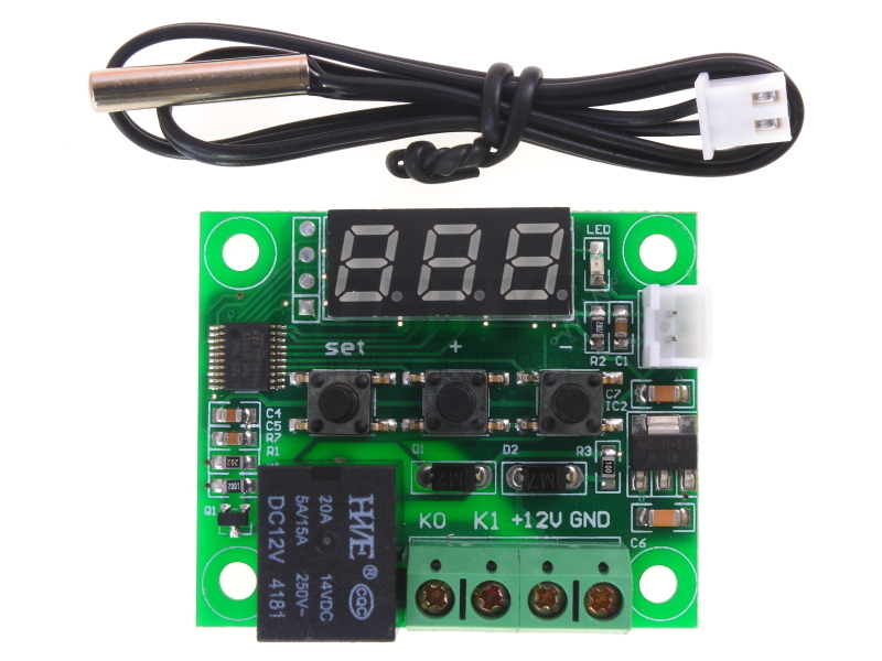
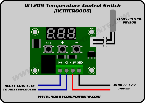
The W1209 is an incredibly low cost yet highly functional thermostat controller. With this module (HCTHER0006) you can intelligently control power to most types of electrical device based on the temperature sensed by the included high accuracy NTC temperature sensor. Although this module has an embedded microcontroller no programming knowledge is required. 3 tactile switches allow for configuring various parameters including on & off trigger temperatures. The on board relay can switch up to a maximum of 240V AC at 5A or 14V DC at 10A. The current temperature is displayed in degrees Centigrade via its 3 digit seven segment display and the current relay state by an on board LED.


Image


Image

Temperature Control Range: -50 ~ 110 C
Resolution at -9.9 to 99.9: 0.1 C
Resolution at all other temperatures: 1 C
Measurement Accuracy: 0.1 C
Control Accuracy: 0.1 C
Refresh Rate: 0.5 Seconds
Input Power (DC): 12V
Measuring Inputs: NTC (10K 0.5%)
Waterproof Sensor: 0.5M
Output: 1 Channel Relay Output, Capacity: 10A

Power Consumption
Static Current: <=35mA
Current: <=65mA

Environmental Requirements
Temperature: -10 ~ 60 C
Humidity: 20-85%

Dimensions
48mm x 40mm x 14mm

Settings Chart
Long press the “SET” button to activate the menu.

Code Description Range Default Value
P0 Heat C/H C
P1 Backlash Set 0.1-15 2
P2 Upper Limit 110 110
P3 Lower Limit -50 -50
P4 Correction -7.0 ~ 7.0 0
P5 Delay Start Time 0-10 mins 0
P6 High Temperature Alarm 0-110 OFF

Long pressing +- will reset all values to their default


Displaying the current temperature:
The thermostat will display the current temperature in oC by default. When in any other mode making no input for approximately 5 seconds will cause the thermostat to return to this default display.

Setting the trigger temperature:
To set the trigger temperature press the button marked 'SET'. The seven segment display will flash. You can now set a trigger temperature (in oC) using the '+' and '-' buttons in 0.1 degree increments. If no buttons are pressed for approximately 2 seconds the trigger temperature will be stored and the display will return back to the current temperature. e578443#

Setting the parameters:
To set any parameter first long press the 'SET' button for at least 5 seconds. The seven segment display should now display 'P0'. This represents parameter P0. Pressing the '+' or '-' buttons will cycle though the various parameters (P0 to P6). Pressing the 'SET' button whilst any of there parameters are displayed will allow you to change the value for that parameter using the '+' and '-' buttons (see below). When finished setting a parameter press the set button to exit that option. If no buttons are pressed for approximately 5 seconds the thermostat will exit the parameter options and will return back to the default temperature display.

Setting the cooling or heating parameter P0:
The parameter P0 has two settings, C and H. When set to C (cooling) the controller will turn on the cooling system to drive the temperature down to the trigger temperature. Once at this temperature the controller will turn off the cooling. When the temperature drifts back to the set point + hysteresis (see parameter P2) the controller will turn the cooling system back on.
When set to H (heating) the controller will turn on a heater to drive the temperature up to the trigger temperature. Once at this temperature the controller will turn the heating off. When the temperature drops back down to the setpoint - hysteresis (see parameter P2) the controller will turn the heating system back on.

Setting the hysteresis parameter P1:
This sets how much change in temperature must occur before the relay will turn back on after reaching the trigger temperature. For example, when in heating mode, if set to the default 2oC and the trigger temperature has been set to 25oC, it will not re-energise the relay until the temperature falls back below below 23oC (25oC - 2oC). Setting this hysteresis helps stop the controller from continually triggering when the temperature drifts around the trip temperature.

Setting the upper limit of the thermostat parameter P2:
This parameter limits the maximum trigger temperature that can be set. It can be used as a safety to stop an excessively high trigger temperature from accidentally being set by the user.

Setting the lower limit of the thermostat parameter P3:
This parameter limits the minimum trigger temperature that can be set. It can be used as a safety to stop an excessively low trigger temperature from accidentally being set by the user.

Setting temperature offset correction parameter P4:
Should you find there is a difference between the displayed temperature and the actual temperature (for instance if the temperature probe is on a long run of cable) you can make minor corrections to the temperature reading with this parameter.

Setting the trigger delay parameter P5:
This parameter allows for delaying switching of the relay when the trigger temperature has be reached. The parameter can be set in one minute increments up to a maximum of 10 minutes.

Setting the high temperature alarm parameter P6:
Setting a value for this parameter will cause the relay to switch off when the the temperature reaches this setting. The seven segment display will also show '---' to indicate an alarm condition. The relay will not re-energise until the temperature falls below this value. The default setting is OFF.


Disclaimer: Libraries, example code, and diagrams are provided as an additional free service by Hobby Components and are not sold as part of this product. We do not provide any guarantees or warranties as to their accuracy or fitness for purpose.

Descriptions and diagrams on this page are copyright Hobby Components Ltd and may not be reproduced without permission.

barewires
Posts: 49
Joined: Wed Aug 21, 2013 7:38 am

Re: W1209 Temperature control Switch (HCTHER0006)

Post by barewires » Tue May 09, 2017 2:58 pm

Reset to default is actually done by holding + and - and then powering up. This module is super value and functional. Even better is the STmicroelectronics microcontroller STM8S003F3P6 is wide open and can be programmed as a development system in C, asm and even FORTH! Caveat emptor, though, for warranty purposes. Having worked with the Intel 4004 in the early 70s, if I were to start over I would buy the W1209 and launch myself into the future, once again. Enjoy.
https://github.com/TG9541/stm8ef/wiki/Board-W1209

Alfredo
Posts: 23
Joined: Sat May 13, 2017 12:43 pm

Re: W1209 Temperature control Switch (HCTHER0006)

Post by Alfredo » Sat May 13, 2017 1:05 pm

Barewires, the GitHub repo you mention gives the temperature control switch board a command line, that's quite surprising! It looks like a programmer and a serial interface adapter are required. Is there something you can recommend?

barewires
Posts: 49
Joined: Wed Aug 21, 2013 7:38 am

Re: W1209 Temperature control Switch (HCTHER0006)

Post by barewires » Sat May 13, 2017 3:57 pm

The programmer is the Hobbycomponents STM8 & STM32 EMULATOR AND PROGRAMMER - Model HCDVBD0016

http://hobbycomponents.com/st-micro-ele ... programmer

I have traced the 4 pin header from top to bottom, located to the left of the LED.

Pin 4 is the GND at the board edge.
Pin 3 goes to pin 4 , ic STM8S003F TSSOP20 = NRST Reset
Pin 2 goes to pin 18, ic STM8S003F TSSOP20 = PD1/SWIM Interface to Debug or Programming
Pin 1 goes to +5.0 Vdc. Designated as square pad.

The external 12 v screw terminal power feeds a diode drop D2 and the AMS1117-5.0 5 volt regulator. If external 12 volt power is used - do not connect Pin 1. I confirmed that back-powering the W1209 alone from the Programmer 5 volt pin is safe and the temperature works normally.

I have had success in other projects, not yet this one, with the HC USB Interface Cable. Once again, take care with the 5v power supplied from the host system USB power. Typically only the send/receive/ground are used. Always use a meter to verify the wire colours (red/black reversed from another supplier - with minus 3.3 volts shown on the PC send signal -which is bad) and the PC send signal is typically at high logic 3.3 volts. http://hobbycomponents.com/usb-interfac ... face-cable

http://www.advanced-monolithic.com/pdf/ds1117.pdf
https://hackaday.io/project/16097-efort ... 8s-gadgets
http://www.st.com/content/ccc/resource/ ... 024550.pdf
http://usefulldata.com/cheap-12v-temper ... be-review/
http://sdcc.sourceforge.net/

I have tried reading the flash but get all 71H, maybe due to program protection.

http://hobbycomponents.com/st-micro-ele ... ment-board
Check out this enhanced product and data for a newer/larger STM8 microcontroller of a similar series.
Last edited by barewires on Mon May 22, 2017 10:52 am, edited 4 times in total.

Alfredo
Posts: 23
Joined: Sat May 13, 2017 12:43 pm

Re: W1209 Temperature control Switch (HCTHER0006)

Post by Alfredo » Sun May 14, 2017 8:34 pm

Hi Barewires, thanks a lot for links and hints! I guess that I'll give it a try.

According to the docs on github the other board you mentioned, HCDVBD0034 with STM8S103F3, is also supported:
https://github.com/TG9541/stm8ef/wiki/S ... kout-board

There is also something on the STM8S105K4T6 which powers the HCDVBD0032
http://hobbycomponents.com/st-micro-ele ... ment-board
https://github.com/TG9541/stm8ef/wiki/S ... kout-board

Here is some code from the link above:

Code: Select all

\ Blinky using the background task
\ To stop it type 0 BG !
: blinky TIM $40 AND 0= OUT! ;
' blinky BG !
Forth seems to be simple but multitasking on a 8bit micro with a console is a surprise!

barewires
Posts: 49
Joined: Wed Aug 21, 2013 7:38 am

Re: W1209 Temperature control Switch (HCTHER0006)

Post by barewires » Wed May 24, 2017 11:07 am

Hi Alfredo and all, I have had much success with eForth on the STM8S103F3 - see HCDVBD0034 forum.
http://forum.hobbycomponents.com/viewto ... =87&t=2180
Last edited by barewires on Wed May 31, 2017 9:44 pm, edited 1 time in total.

barewires
Posts: 49
Joined: Wed Aug 21, 2013 7:38 am

Re: W1209 Temperature control Switch (HCTHER0006)

Post by barewires » Fri May 26, 2017 12:54 am

Finally I have programmed the W1209 with the eForth OS. The factory code is protected and cannot be read or written to unless it is unlocked.
Checkout the HCDVBD0034 forum for details on installing the stm8flash burning utility.

Download the binary files from:
https://github.com/TG9541/stm8ef/releas ... 2.2.10.zip and extract W1209.ihx

.ihx is in Intel Hex format and can be viewed with less W1209.ihx scroll up/dn, q to quit. Less is better than More as in cat W1209.ihx | more space to advance a page only to fall through the end.

I have calculated the overhead in the hex file by viewing the last line as a template :00000001FF which is a null terminator and contains 11 characters and includes a hidden Linux format Carriage Return (no LF - this is not MS-DOS remember.) Do a word count

Code: Select all

wc W1209.ihx 
  172   172 12906 W1209.ihx
prints lines, words, and byte counts man wc for help file. There are two ascii characters per byte.
The formula is: number of bytes to burn = (bytes - (lines * 12)) /2 so (12906-(172*12))/2 = 5421 bytes which corresponds to the report from the blaster. In eForth

Code: Select all

12906 172 12 * - 2/ . <enter> 5421 
It is typical that the 4 wire SWIM interface is never 1:1, always verify the positions of the signals. Equally important is Vdd which is detirmined by looking at the voltage regulator part number, often on the back side. 5.0 or 3.3 volts? The W1209 has an AMS1117-5.0 which is powered from 12v external and other boards are running on 5 volts regulated down to 3.3 v. It is usually safe to program by backfeeding at the rated voltage, but be warned.

On a Pi 3 or Pi Zero W: note the W1209 blaster part designation stm8s003?3 and the question mark and the dash small letter L for list below.

Code: Select all

cd ~/stm8flash
./stm8flash -l | grep stm8s003
... stm8s003?3 ...

echo "00 00 ff 00 ff 00 ff 00 ff 00 ff" | xxd -r -p > factory_defaults.bin
sudo ./stm8flash -c stlinkv2 -p stm8s003?3 -s opt -w factory_defaults.bin
sudo ./stm8flash -c stlinkv2 -p stm8s003?3 -s flash -w W1209.ihx
In a few seconds the LED should display 4th meaning eForth is running - celebrate now! :mrgreen: but when you sober up you will realise that the temperature and thermostat code is gone! :shock: but that tends to happen when one installs a new program over the existing. So start reverse engineering and build a new eForth system.

Now I have to evaluate the terminal interface with the following concerns: 1. The serial data uses half-duplex, meaning it is a single lane bridge and traffic takes turns. 2. The SWIM pin

- to be continued as I have not yet had success with the W1209 serial communications.
Sorry for the image quality, it is difficult to get the multiplexed LED segments.
You do not have the required permissions to view the files attached to this post.
Last edited by barewires on Sat Jun 03, 2017 1:22 pm, edited 3 times in total.

Alfredo
Posts: 23
Joined: Sat May 13, 2017 12:43 pm

Re: W1209 Temperature control Switch (HCTHER0006)

Post by Alfredo » Sun May 28, 2017 4:40 pm

Barewires,

did you try using Picocom on the RaspPi as described in the docs? The page links to a Forth code transfer tool written in Python. https://github.com/TG9541/stm8ef/wiki/S ... forth-code

After flashing Forth the W1209 is "naked" but there is some example code, e.g. some kind of interactive pulse generator https://github.com/TG9541/stm8ef/wiki/B ... -generator

You're right, there is no thermostat code on the github site but programming one shouldn't be difficult (once the voltage-to-temperature is known). The linearisation code here looks like it's usable https://github.com/TG9541/stm8ef/wiki/B ... ly-control

Of course, some kind of UI is needed, e.g. for setting thresholds. Judging from the code examples that shouldn't be hard.

barewires
Posts: 49
Joined: Wed Aug 21, 2013 7:38 am

Re: W1209 Temperature control Switch (HCTHER0006)

Post by barewires » Sun May 28, 2017 5:45 pm

Hi Alfredo, I tried picocom a few days ago but lost the link to the page with the configuration settings or 'wrapper', thanks for reminding me.
The sudo is initially included here as it will be required the next time one edits the shell .sh file or else the changes will not be accepted. It can be very frustrating creating a shell file, changing to executable +x and then making lots of changes that don't save.

Code: Select all

cd
sudo nano ./picocomwrapper.sh

#!/bin/sh
#    "$@" --imap lfcrlf --emap crcrlf --omap delbs \
exec picocom \
    --send-cmd="ascii-xfr -s -c10 -l500" \
    "$@" --imap igncr,lfcrlf --omap delbs \
    /dev/ttyUSB0

ctrl-x, y to exit

sudo chmod +x ./picocomwrapper.sh

./picocomwrapper.sh
Now the carriage return / line feed works normally in interactive mode (still missing when in NVM / RAM entry mode?) with CR being generated locally by picocom on the STM8S dev boards.

stm8eForth v2.2
hi
stm8eForth v2.2
ok

Now I have created a file called TimerForth with the contents : - - - ; shown below. Simply pasting the code directly is too fast so I used Ctrl-A, Ctrl-S,
in picocom, 'S' for send file. The -c is character delay and -l is line delay to allow eForth time to compile the words. I will later investigate why the terminal runs only at 9600 baud. As I have the MINDEV source code it is worth learning. If you want to save the new words in Flash then type NVM for Non Volatile Memory.

First type FILE to go into file transfer mode. The eForth command FILE puts the system into a mode that does not echo back nor sends out error messages and HAND goes back to interactive mode. This is used to best transfer files.

Ctrl-A Ctrl-S
*** file: TimerForth
ascii-xfr -s -c10 -l500 TimerForth
ASCII upload of "TimerForth"
Line delay: 500 ms, character delay 10 ms

: b1 TIM 1 AND 0= OUT! ; \ 99.24 Hz symmetrical
: b2 TIM 2 AND 0= OUT! ; \ 49.63 sym
: b3 TIM 3 AND 0= OUT! ; \ 49.63 LED low = on 25%
: b4 TIM 4 AND 0= OUT! ; \ 24.815 sym
: b5 TIM 5 AND 0= OUT! ; \ 49.637 2 low pulses
: b7 TIM 7 AND 0= OUT! ; \ 24.815
: b8 TIM 8 AND 0= OUT! ; \ 12.408 sym
: b10 TIM 10 AND 0= OUT! ; \ 24.81 2 low pulses @ 10 ms
: b15 TIM 15 AND 0= OUT! ; \ 12.408 1 low pulse 5 mS period 80 ms duty 6.25% LED low = on
: b16 TIM 16 AND 0= OUT! ; \ 6.2 Hz sym
: b32 TIM 32 AND 0= OUT! ; \ period 322 ms sym
: b64 TIM 64 AND 0= OUT! ; \ period 645 ms sym
: b128 TIM 128 AND 0= OUT! ; \ period 1.29 s sym
: bAA TIM $AA AND 0= OUT! ; \ 4 low pulses @ 10 ms 10101010 binary = AA hex
: b55 TIM $55 AND 0= OUT! ; \ period 160 ms 4 low pulses @ 5 ms 01010101 binary = 55 hex
: b255 TIM 255 AND 0= OUT! ; \ period 1.29 s 1 low pulse
*** exit status: 0
Now type HAND to go back into interactive mode. Turn off NVM by typing RAM.

/Background blinking is started as follows:
' b128 BG ! / to load timer value and blink
0 BG ! / to stop blinking

I have yet to get a working terminal with the W1209 board, so the contents of these posts mostly applies to parallel eForth threads now working on other HC STM8S board series.
Updating the forum accurately and sharing information is more labour intensive than actually doing it.
Still need to see if a diode is needed when using the SWIM pin as a half-duplex link on the W1209.
Last edited by barewires on Mon Jun 19, 2017 4:05 pm, edited 13 times in total.

barewires
Posts: 49
Joined: Wed Aug 21, 2013 7:38 am

Re: W1209 Temperature control Switch (HCTHER0006)

Post by barewires » Sun May 28, 2017 6:35 pm

Also running gforth on the Pi, it is a full Forth with 1763 words.

sudo apt-get install -y gforth
gforth
words

//copy and paste the list of words with editing to a file gforthwords. (Raspbian / Linux does not care about file extensions (it's all in the permissions) so this file can be viewed with less gforthwords.

wc gforthwords
187 1763 15740 gforthwords
1763 vs 162 eForthwords. Of course the 8K / 1K STM8S is punching above its weight with my Pi Zero W at 16 GB / 512M and a 250 GB PiDrive.

One enhanced command is see, an ARM disassembler, see DROP or any other word. This word is far to complex to put in a small micro.
See also can look at itself see see
: see
parse-name find-name dup 0=
IF drop -13 throw
THEN
name-see ; ok
A great way to learn how words are written.

Post Reply

Return to “Sensors”