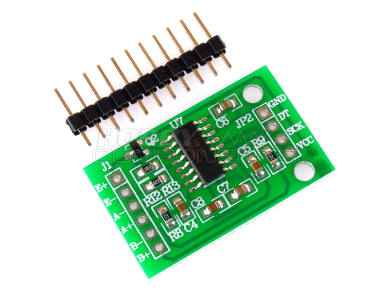
A very low cost module incorporating with a very high precision 24 ADC and differential high gain inputs designed to be interfaced with many common types of bridge sensors. E.g. pressure, strain, weight sensors.
Based on Avia Semiconductor’s patented technology, HX711 is a precision 24-bit analogue to-digital converter (ADC) designed for weigh scales and industrial control applications to interface directly with a bridge sensor. The input multiplexer selects either Channel A or B differential input to the low-noise programmable gain amplifier (PGA). Channel A can be programmed with a gain of 128 or 64, corresponding to a full-scale differential input voltage of ±20mV or ±40mV respectively, when a 5V supply is connected to AVDD analogue power supply pin. Channel B has a fixed gain of 32. On-chip power supply regulator eliminates the need for an external supply regulator to provide analogue power for the ADC and the sensor. There is no programming needed for the internal registers. All controls to the HX711 are through the pins.
Features:
• Two selectable differential input channels
• On-chip active low noise PGA with selectable gain of 32, 64 and 128
• On-chip power supply regulator for load-cell and ADC analogue power supply
• On-chip oscillator requiring no external component with optional external crystal
• On-chip power-on-reset
• Simple digital control and serial interface: pin-driven controls, no programming needed
• Simultaneous 50 and 60Hz supply rejection
• Current consumption including on-chip analogue power supply regulator: normal operation < 1.5mA, power down < 1uA
• Operation supply voltage range: 2.6 ~ 5.5V
• Operation temperature range: -40 ~ +85oC
Example:

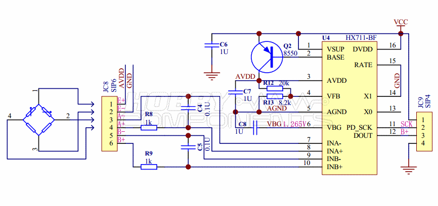
Schematic:
Example Arduino Sketch:
Code: Select all
/* FILE:    HX711_Bridge_Sensor_Digital_Interface_Module
   DATE:    28/08/14
   VERSION: 0.1
   AUTHOR:  Andrew Davies

This is a basic example of how to use the HX711 dual channel bridge sensor interface
module (HCMODU0073). By default the sketch will configure the module to take
measurements from the channel A input with a gain of 64. These measurements will be
repeatedly triggered at its maximum rate and the result output to a serial terminal.

PINOUT:

Module.....Uno/Nano
GND........GND
DT.........D9
SCK........D8
VCC........+5V


You may copy, alter and reuse this code in any way you like, but please leave
reference to HobbyComponents.com in your comments if you redistribute any part of
this code. This software may not be used for the purpose of promoting products
that directly compete with Hobby Components Ltd's own range of products.

THIS SOFTWARE IS PROVIDED "AS IS". HOBBY COMPONENTS MAKES NO WARRANTIES, WHETHER
EXPRESS, IMPLIED OR STATUTORY, INCLUDING, BUT NOT LIMITED TO, IMPLIED WARRANTIES OF
MERCHANTABILITY AND FITNESS FOR A PARTICULAR PURPOSE, ACCURACY OR LACK OF NEGLIGENCE.
HOBBY COMPONENTS SHALL NOT, IN ANY CIRCUMSTANCES, BE LIABLE FOR ANY DAMAGES,
INCLUDING, BUT NOT LIMITED TO, SPECIAL, INCIDENTAL OR CONSEQUENTIAL DAMAGES FOR ANY
REASON WHATSOEVER.
*/


/* Define digital pins used for the clock and data signals. */
#define PD_SCK 8
#define DOUT 9

/* Define the various gain and input options */
#define CHAN_A_GAIN_128 1
#define CHAN_B_GAIN_32 2
#define CHAN_A_GAIN_64 3


void setup()
{
  Serial.begin(9600);

  /* Set the clock pin to and output and the digital pin to an input */
  pinMode(PD_SCK, OUTPUT);
  pinMode(DOUT, INPUT);

   /* Take the device out of power down mode (clock pin low) */
  digitalWrite(PD_SCK, LOW);

  /* Trigger a conversion so that the module is in the correct mode for
     the next measurement */
  ReadConversion(CHAN_A_GAIN_64);
}

/* Main program loop */
void loop()
{
  /* Read in the last measurement and output to the serial port */
  Serial.println(ReadConversion(CHAN_A_GAIN_64));
}


/* Function to read a measurement from the module.
   The result is returned as a 32 bit signed integer */
long ReadConversion(byte ConversionMode)
{
  byte index;
  long ConversionData = 0L;

  /* Read in the 24 bit conversion data */
  while(digitalRead(DOUT));
  for (index = 0; index < 24; index++)
  {
    digitalWrite(PD_SCK, HIGH);
    ConversionData =  (ConversionData << 1) | digitalRead(DOUT);
    digitalWrite(PD_SCK, LOW);
  }

  /* Output some extra clock cycles to set the gain and input options */
  for (index = 0; index < ConversionMode; index++)
  {
    digitalWrite(PD_SCK, HIGH);
    digitalWrite(PD_SCK, LOW);
  }

  /* Number is returned as a 24bit 2's compliment but we need to
     convert it to convert to 32 bit singed integer */
  if (ConversionData >= 0x800000)
    ConversionData = ConversionData | 0xFF000000L;

  return ConversionData ;
}
Datasheet: