Description:
The GY-5150 (HCMODU0064) is a breakout module for the MPU-9150 9 - axis accelerometer, gyroscope, and digital compass (magnetometer) I.C. The MPU-9150 is the world’s first integrated 9-axis Motion Tracking device that combines a 3-axis MEMS gyroscope, a 3-axis MEMS accelerometer, a 3-axis MEMS magnetometer and a Digital Motion Processor™ (DMP™) hardware accelerator engine. The MPU-9150 is an ideal solution for handset and tablet applications, game controllers, motion pointer remote controls, and other consumer devices. The MPU-9150’s 9-axis MotionFusion combines acceleration and rotational motion plus heading information into a single data stream for the application. This MotionProcessing™ technology integration provides a smaller footprint and has inherent cost advantages compared to discrete gyroscope, accelerometer, plus magnetometer solutions. The MPU-9150 is also designed to interface with multiple non-inertial digital sensors, such as pressure sensors, on its auxiliary I2C port to produce a 10-Axis sensor fusion output. The MPU-9150 is a 3rd generation motion processor and is footprint compatible with the MPU-60X0 and MPU- 30X0 families. The MPU-9150 features three 16-bit analog-to-digital converters (ADCs) for digitizing the gyroscope outputs, three 16-bit ADCs for digitizing the accelerometer outputs and three 13-bit ADCs for digitising the magnetometer outputs. For precision tracking of both fast and slow motions, the parts feature a userprogrammable gyroscope full-scale range of ±250, ±500, ±1000, and ±2000°/sec (dps), a user programmable accelerometer full-scale range of±2g, ±4g, ±8g, and ±16g, and a magnetometer full-scale range of ±1200μT. The MPU-9150 is a multi-chip module (MCM) consisting of two dies integrated into a single LGA package. One die houses the 3-Axis gyroscope and the 3-Axis accelerometer. The other die houses the AK8975 3- Axis magnetometer from Asahi Kasei. Communication with all registers of the device is performed using I2C at 400kHz. Additional features include an embedded temperature sensor and an on-chip oscillator with ±1% variation over the operating temperature range.
Gyroscope Features:
The triple-axis MEMS gyroscope in the MPU-9150 includes a wide range of features:
• Digital-output X-, Y-, and Z-Axis angular rate sensors (gyroscopes) with a user-programmable fullscale
range of ±250, ±500, ±1000, and ±2000°/sec
• External sync signal connected to the FSYNC pin supports image, video and GPS synchronization
• Integrated 16-bit ADCs enable simultaneous sampling of gyros
• Enhanced bias and sensitivity temperature stability reduces the need for user calibration
• Improved low-frequency noise performance
• Digitally-programmable low-pass filter
• Factory calibrated sensitivity scale factor
• User self-test
Accelerometer Features:
The triple-axis MEMS accelerometer in MPU-9150 includes a wide range of features:
• Digital-output 3-Axis accelerometer with a programmable full scale range of ±2g, ±4g, ±8g and ±16g
• Integrated 16-bit ADCs enable simultaneous sampling of accelerometers while requiring no external
multiplexer
• Orientation detection and signaling
• Tap detection
• User-programmable interrupts
• High-G interrupt
• User self-test
Magnetometer Features:
The triple-axis MEMS magnetometer in MPU-9150 includes a wide range of features:
• 3-axis silicon monolithic Hall-effect magnetic sensor with magnetic concentrator
• Wide dynamic measurement range and high resolution with lower current consumption.
• Output data resolution is 13 bit (0.3 μT per LSB)
• Full scale measurement range is ±1200 μT
• Self-test function with internal magnetic source to confirm magnetic sensor operation on end
products
Additional Features:
The MPU-9150 includes the following additional features:
• 9-Axis MotionFusion via on-chip Digital Motion Processor (DMP)
• Auxiliary master I2C bus for reading data from external sensors (e.g., pressure sensor)
• Flexible VLOGIC reference voltage supports multiple I2C interface voltages
• Smallest and thinnest package for portable devices: 4x4x1mm LGA
• Minimal cross-axis sensitivity between the accelerometer, gyroscope and magnetometer axes
• 1024 byte FIFO buffer reduces power consumption by allowing host processor to read the data in
bursts and then go into a low-power mode as the MPU collects more data
• Digital-output temperature sensor
• User-programmable digital filters for gyroscope, accelerometer, and temp sensor
• 10,000 g shock tolerant
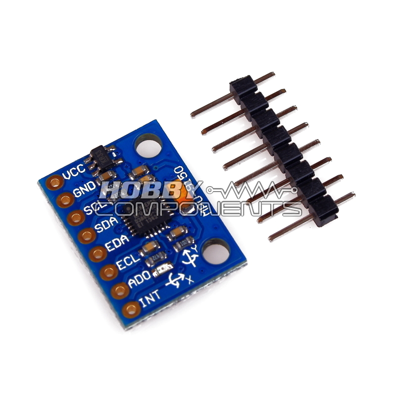
Module Pinout:
VCC......3.6 to 6V supply (on-board 3.3V regulator)
GND......0V
SCL......I2C serial clock
SDA......I2C serial data
EDA......Auxiliary I2C master serial data
ECL......Auxiliary I2C Master serial clock
AD0......I2C Slave Address LSB (AD0)
INT......Interrupt digital output (totem pole or open-drain)
Example Arduino Sketch:
Code: Select all
/* FILE:    ARD_GY_5150_MPU9150_Example
   DATE:    22/05/14
   VERSION: 0.1

REVISIONS:

22/05/14 Created version 0.1

This is an example of how to use the Hobby Components GY-5150 / MPU9150
accelerometer, gyro, compass (magnetometer) module (HCMODU0064). The MPU9150 has
many advanced features however this example sketch is written to show the basic steps
required to obtain reading from all three sensors and the additional temperature sensor.
The sketch will repeatedly read measurements from each axis of all three sensors plus
the additional temperature sensor and output them to the serial port.

PINOUT:

MODULE`                Arduino
VCC                    +5V
GND                    GND
SCL                    A5*
SDA                    A4*
EDA                    N/A
ECL                    N/A
AD0                    N/A
INT                    N/A

*Please note that the MPU9150 operates at 3.3V (via a 3.3V regulator) and these
pins should not be driven above 3.8V therefore you may require level shifters to
ensure safe operation. These two pins also include 220R pull-up resistors.

You may copy, alter and reuse this code in any way you like, but please leave
reference to HobbyComponents.com in your comments if you redistribute this code.
This software may not be used for the purpose of promoting or selling products
that directly compete with Hobby Components Ltd's own range of products.

THIS SOFTWARE IS PROVIDED "AS IS". HOBBY COMPONENTS MAKES NO WARRANTIES, WHETHER
EXPRESS, IMPLIED OR STATUTORY, INCLUDING, BUT NOT LIMITED TO, IMPLIED WARRANTIES OF
MERCHANTABILITY AND FITNESS FOR A PARTICULAR PURPOSE, ACCURACY OR LACK OF NEGLIGENCE.
HOBBY COMPONENTS SHALL NOT, IN ANY CIRCUMSTANCES, BE LIABLE FOR ANY DAMAGES,
INCLUDING, BUT NOT LIMITED TO, SPECIAL, INCIDENTAL OR CONSEQUENTIAL DAMAGES FOR ANY
REASON WHATSOEVER.
*/

/* I2C addresses of Accelerometer/Gyro and Compass */
#define I2CACCGYROADD 0x68
#define I2CCOMPADD 0x0C

/* Accelerometer/Gyro register addresses */
#define ACCEL_CONFIG 0x1C
#define GYRO_CONFIG 0x1B
#define ACCEL_XOUT_H 0x3B
#define ACCEL_YOUT_H 0x3D
#define ACCEL_ZOUT_H 0x3F
#define TEMP_OUT_H 0x41
#define GYRO_XOUT_H 0x43
#define GYRO_YOUT_H 0x45
#define GYRO_ZOUT_H 0x47
#define PWR_MGMT_1 0x6B

/*Compass register addresses */
#define COMP_STATUS 0x02
#define COMP_XOUT_L 0x03
#define COMP_YOUT_L 0x05
#define COMP_ZOUT_L 0x07

/* Accelerometer range modes */
#define ACCELRANGE_2g 0
#define ACCELRANGE_4g 1
#define ACCELRANGE_8g 2
#define ACCELRANGE_16g 3

/* Gyroscope sensitivity */
#define GYRORANGE_250DPS 0
#define GYRORANGE_500DPS 1
#define GYRORANGE_1000DPS 2
#define GYRORANGE_2000DPS 3

/* Include the standard wire library */
#include <Wire.h>

void setup()
{
  /* Initialise the I2C bus */
  Wire.begin();

  /* Initialise the serial interface */
  Serial.begin(9600);

  /* Initialise the accelerometer and gyro and put the I2C bus into pass-through mode*/
  Initalise_AccelGyro(ACCELRANGE_8g, GYRORANGE_2000DPS);
}

/* Main program */
void loop()
{

  /* Read the temperature sensor and send it to the serial port */
  Serial.print("Temp: ");
  Serial.print((double)(Read_Acc_Gyro(TEMP_OUT_H) + 11900) / 340);
  Serial.print(" ");

  /* Read the accelerometer X, Y, and Z axis and send it to the serial port */
  Serial.print("Acc X: ");
  Serial.print(Read_Acc_Gyro(ACCEL_XOUT_H));
  Serial.print(" Acc Y: ");
  Serial.print(Read_Acc_Gyro(ACCEL_YOUT_H));
  Serial.print(" Acc Z: ");
  Serial.print(Read_Acc_Gyro(ACCEL_ZOUT_H));

  /* Read the gyroscope X, Y, and Z axis and send it to the serial port */
  Serial.print(" Gyro X: ");
  Serial.print(Read_Acc_Gyro(GYRO_XOUT_H));
  Serial.print(" Gyro Y: ");
  Serial.print(Read_Acc_Gyro(GYRO_YOUT_H));
  Serial.print(" Gyro Z: ");
  Serial.print(Read_Acc_Gyro(GYRO_ZOUT_H));

  /* Trigger a compass measurement */
  Trigger_Compass();

  /* Read the compass X, Y, and Z axis and send it to the serial port */
  Serial.print(" Comp X: ");
  Serial.print(Read_Compass(COMP_XOUT_L));
  Serial.print(" Comp Y: ");
  Serial.print(Read_Compass(COMP_YOUT_L));
  Serial.print(" Comp Z: ");
  Serial.println(Read_Compass(COMP_ZOUT_L));
}


/* Read one of the accelerometer or gyro axis registers */
int Read_Acc_Gyro(byte axis)
{
  int Data;

  /* Select the required register */
  Wire.beginTransmission(I2CACCGYROADD);
  Wire.write(axis);
  Wire.endTransmission();

  /* Request the high and low bytes for the required axis */
  Wire.requestFrom(I2CACCGYROADD, 2);
  Data = (int)Wire.read() << 8;
  Data = Data | Wire.read();
  Wire.endTransmission();

  return Data;
}


/* Initialises the accelerometer and gyro to one of the sensitivity
   ranges and puts the I2C bus into pass-through mode */
void Initalise_AccelGyro(byte Accel_Range, byte Gyro_Range)
{
  /* Take the MPU9150 out of sleep */
  Wire.beginTransmission(I2CACCGYROADD);
  Wire.write(PWR_MGMT_1);
  Wire.write(0);
  Wire.endTransmission();

  /* Set the sensitivity of the module */
  Wire.beginTransmission(I2CACCGYROADD);
  Wire.write(ACCEL_CONFIG);
  Wire.write(Accel_Range << 3);
  Wire.endTransmission();

  /* Set the sensitivity of the module */
  Wire.beginTransmission(I2CACCGYROADD);
  Wire.write(GYRO_CONFIG);
  Wire.write(Gyro_Range << 3);
  Wire.endTransmission();

  /* Put the I2C bus into pass-through mode so that the aux I2C interface
     that has the compass connected to it can be accessed */
  Wire.beginTransmission(I2CACCGYROADD);
  Wire.write(0x6A);
  Wire.write(0x00);
  Wire.endTransmission(true);

  Wire.beginTransmission(I2CACCGYROADD);
  Wire.write(0x37);
  Wire.write(0x02);
  Wire.endTransmission(true);
}


/* Read one of the compass axis */
int Read_Compass(byte axis)
{
  int Data;

  /* Select the required axis register */
  Wire.beginTransmission(I2CCOMPADD);
  Wire.write(axis);
  Wire.endTransmission();

  /* Request the low and high bytes for the required axis */
  Wire.requestFrom(I2CCOMPADD, 2);
  Data = Wire.read();
  Data = Data | (int)(Wire.read() << 8);
  Wire.endTransmission();

  return Data;
}


/* Trigger a single shot compass reading of all three axis */
void Trigger_Compass(void)
{

  /* Trigger a measurement */
  Wire.beginTransmission(I2CCOMPADD);
  Wire.write(0x0A);
  Wire.write(0x01);
  Wire.endTransmission(true);

  /* Wait for the measurement to complete */
  do
  {
    Wire.beginTransmission(I2CCOMPADD);
    Wire.write(COMP_STATUS);
    Wire.endTransmission();

    Wire.requestFrom(I2CCOMPADD, 1);
  }while(!Wire.read());
}