Features:
Using pyroelectric PIR sensor, Fresnel
Low-power, static power 65uA
Wide voltage range, DC 5V-20V
Board small size 38 * 28mm (32 * 24 * mm)
Repeatable / not repeatable trigger mode selection
Easy to use, power + - signal output
7 m sensing range
110 ° angle sensor
Electrical Parameters:
Operating voltage range of 5-20V DC voltage
65uA quiescent current
High output level 3.3 V / Low 0V
Non-repeatable trigger L trigger / H Repeat Trigger
PCB dimensions 38 * 28mm (32 * 24 * mm)
110 ° angle sensor
7 m sensing range
Applications:
Security products, Toys, body sensor lighting control, industrial automation
Pyroelectric infrared switch BISS0001 accompanied by a pyroelectric infrared sensor and a small amount of external components, consisting of passive infrared
Sensing of a security zone for automatic lighting, lighting and alarm systems.
Pinout (connector side):
1....VCC (5-20V)
2....DIGITAL OUT (10mA Max)
3....GND
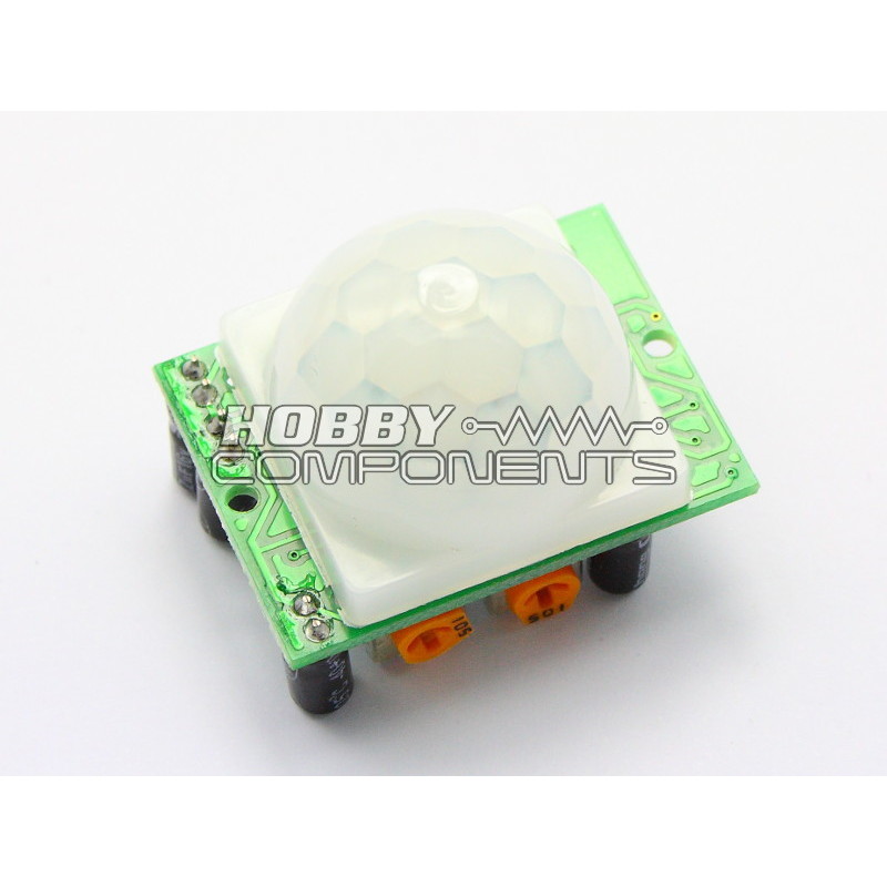
Potentiometers:
1...Sensitivity
2...Trigger time