Description:
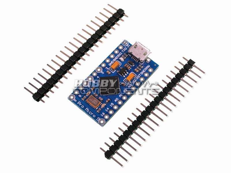
The Pro Micro is similar to the Pro Mini, except for the fact that it utilises the ATMega32U4. Additionally, there is an on-board USB transceiver inside the 32U4, which removes the need for a bulky external USB interface. There is also a voltage regulator on-board which means it can accept up to 12V DC. Please bear in mind that if supplying unregulated power, you need to connect to “RAWâ€, not “VCCâ€.
The pro micro is available to two versions, 3.3V and 5V:
3.3V Version:
Product Code: HCDVBD0024
Supply voltage (VCC): 3.3V
Supply voltage (RAW): 3.6V - 12V
Frequency: 8MHz
Dimensions: 1.3 x 0.7"
Order the 3.3V Version Here.
5V Version:
Product Code: HCDVBD0013
Supply voltage (VCC): 5V
Supply voltage (RAW): 5.3V - 12V
Frequency: 16MHz
Dimensions: 1.3 x 0.7"
Order the 5V Version Here.
Features:
• ATMega 32U4 running at 5V/16MHz or 3.3V/8MHz (depending on version)
• Supported under Arduino IDE
• On-Board micro-USB connector for programming
• 4 x 10-bit ADC pins
• 12 x Digital I/Os (5 are PWM capable)
• Rx and Tx Hardware Serial Connections
This product is manufactured by Deek-Robot and is derived from the SparkFun(TM) Pro Mini reference design which was released under the Creative commons Attribution-ShareAlike 3.0 licence.
https://creativecommons.org/licenses/by ... /legalcode
Files:
As of writing this post, the current Arduino development environment does not directly support the Pro Micro; but adding support is very simple. First of all you will need to download a zip file containing drivers and hardware files. This can be downloaded from the SparkFun website here, or a current known working snapshot can be downloaded directly from this post below:
Uzip this folder and place it in the 'Hardware' folder contained within your Arduino development environments working folder. By default this is usually C:\Users\Username\Documents\Arduino\Hardware (assuming you are using windows). If you don't see a hardware folder, just create one. Within this unziped folder you will see a driver folder that contains a driver for your Pro Micro.
Schematic:
Modified Blink Sketch:
Code: Select all
/*
  Blink
  Turns on an LED on for one second, then off for one second, repeatedly.

  This example code is in the public domain.
 */

// Pin 13 has an LED connected on most Arduino boards.
// give it a name:
int led = 17;

// the setup routine runs once when you press reset:
` setup() {
  // initialize the digital pin as an output.
  pinMode(led, OUTPUT);
}

// the loop routine runs over and over again forever:
void loop() {
  digitalWrite(led, HIGH);   // turn the LED on (HIGH is the voltage level)
  delay(100);               // wait for a second
  digitalWrite(led, LOW);    // turn the LED off by making the voltage LOW
  delay(100);               // wait for a second
}Why are there only 5 PWM channels when other Arduino 13U4 based boards have 7?
This is because the 2 PWM channels that would normally be available on header pins D11 and D13 are not routed out on this board. They are still there but you would have to solder directly to the pins on the device, hence not being advertised as useable.
Why does the USB interface disappear and reappear when I program or reset my board?
It is normal for the USB port on a Leonardo to disappear whilst in the programming process, or when it is reset. This is because the main processor handles the USB interface itself via software emulation. Therefore if it is manually reset, or reset by the programming process this software emulation stops running and the USB port is temporarily lost while the Arduino bootloader reboots. There is a section on the Arduino website that explains this in more detail here: http://arduino.cc/en/Guide/ArduinoLeona ... noLeonardo
What is the maximum current I can draw from the 5V regulator?
The manufacture of the regulator specs a maximum of 400mA. Please bear in mind that this maximum is based on ideal operating conditions. As a general rule of thumb, if the regulator is getting hot to the touch then you are probably drawing too much power from it. Under normal loads the regulator should stay cool/slightly warm to the touch.