
Arduino library header for the ADS1015, ADS1113, ADS1114, & ADS1115 serial analogue to digital devices. Currently supported products:
ADS1015 I2C 12Bit ADC Module (HCMODU0099) available from hobbycomponents.com
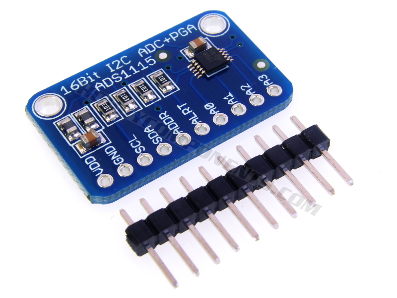
ADS1115 I2C 16Bit ADC Module (HCMODU0098) available from hobbycomponents.com
This Arduino library can be used to configure and obtain measurements from the Texas Instruments ADS1015, ADS1113, ADS1114, & ADS1115 16bit serial ADC devices.
You will need to download (please log in to download the library) and unzip this library to the Arduino development environments library area.
On Windows:
My Documents\Arduino\libraries\
On Mac:
Documents/Arduino/libraries/
Linux:
Usually found within the users home area under /Arduino/libraries/
Using the HCADS1xxx library
To use the library just include the HCADS1xxx.h header file and then create an instance of the library. E.g:
Code: Select all
#include "HCADS1xxx.h"
HCADS1xxx HCADS1xxx(ADS1xxx_I2C_ADD_LOW);
The ADS111x devices and our module can be set to one of 4 I2C address which are dependent on the state of the sensors address select pin (ADDR ), or the address selection pin on the HCMODU098. This can be in one of four states, low, high, connected to SDA, or connected to SCL:
ADS1xxx_I2C_ADD_LOW (I2C address: 0x48)
ADS1xxx_I2C_ADD_HIGH (I2C address: 0x49)
ADS1xxx_I2C_ADD_SDA (I2C address: 0x4A)
ADS1xxx_I2C_ADD_SCL (I2C address: 0x49)
By default the HCMODU0098 & HCMODU0099 module is set to ADS1xxx_I2C_ADD_LOW.
To initialise the library add the following line to the setup() section of your sketch:
Code: Select all
HCADS1xxx.Init();The following functions are available with this library:
Code: Select all
HCADS1xxx.StartConversion();Triggers a new conversion when in single shot mode. The device will power up, make one measurement and then automatically go back in to low power mode.
Code: Select all
int Result = Read();Returns a 16 bit signed 2's compliment integer value representing the last conversion result.
Note for the ADS1015 the 12 bit result is contained in upper bits (bits 4 to 15) with lower 4 bits set to 0's.
Code: Select all
boolean State = HCADS1xxx.ConversionState();Returns a boolean value representing the current conversion state where:
false = device is currently performing a conversion
true = device is not currently performing a conversion.
Code: Select all
HCADS1xxx.Input(Mode);Mode is the required multiplexer state. Valid values are
A0_A1 (measures the differential voltage between pins A0 & A1)
A0_A3 (measures the differential voltage between pins A0 & A3)
A1_A3 (measures the differential voltage between pins A1 & A3)
A2_A3 (measures the differential voltage between pins A2 & A3)
A0 (measures the voltage at pin A0 with reference to GND)
A1 (measures the voltage at pin A1 with reference to GND)
A2 (measures the voltage at pin A2 with reference to GND)
A3 (measures the voltage at pin A3 with reference to GND)
Code: Select all
HCADS1xxx.FullScale(Voltage);Voltage is the required setting for the full scale voltage. Valid values are
FS_6_144V (full scale voltage is set 6.144 Volts)
FS_4_096V (full scale voltage is set 4.096 Volts)
FS_2_048V (full scale voltage is set 2.048 Volts)
FS_1_024V (full scale voltage is set 1.024 Volts)
FS_0_512V (full scale voltage is set 0.512 Volts)
FS_0_256V (full scale voltage is set 0.256 Volts)
Code: Select all
HCADS1xxx.Conv_Mode(Mode);Mode is the required conversion mode. Valid values are
CONTINUOUS (the device will make continuous measurements of the input)
SINGLE_SHOT (the device will make one measurement of the input and then power down)
Code: Select all
HCADS1xxx.Data_Rate(Rate);Rate is the required conversion rate. Valid values for ADS111x devices are
ADS1115_DR_8SPS (conversion rate is set to 8 samples per second)
ADS1115_DR_16SPS (conversion rate is set to 16 samples per second)
ADS1115_DR_32SPS (conversion rate is set to 32 samples per second)
ADS1115_DR_64SPS (conversion rate is set to 64 samples per second)
ADS1115_DR_128SPS (conversion rate is set to 128 samples per second)
ADS1115_DR_250SPS (conversion rate is set to 250 samples per second)
ADS1115_DR_475PS (conversion rate is set to 475 samples per second)
ADS1115_DR_860SPS (conversion rate is set to 860 samples per second)
For the ADS1015 device:
ADS1015_DR_128SPS 0 (conversion rate is set to 128 samples per second)
ADS1015_DR_250SPS 1 (conversion rate is set to 250 samples per second)
ADS1015_DR_490SPS 2 (conversion rate is set to 490 samples per second)
ADS1015_DR_920SPS 3 (conversion rate is set to 920 samples per second)
ADS1015_DR_1600SPS 4 (conversion rate is set to 1600 samples per second)
ADS1015_DR_2400SPS 5 (conversion rate is set to 2400 samples per second)
ADS1015_DR_3300SPS 6 (conversion rate is set to 3300 samples per second)
Code: Select all
HCADS1xxx.Comp_Mode(Mode);Mode is the required mode. Valid values are
HYSTERESIS (traditional comparator with hysteresis)
WINDOWED (window comparator)
Code: Select all
HCADS1xxx.Comp_Pol(Mode);Mode is the required active state of the pin. Valid values are
ACTIVE_LOW (sets pin to active low state)
ACTIVE_HIGH (sets pin to active high state)
Code: Select all
HCADS1xxx.Comp_Lat(Mode);Mode is latching state of the pin. Valid values are
NON_LATCHING (non-latching comparator)
LATCHING (latching comparator)
Code: Select all
HCADS1xxx.Comp_Que(Mode)Mode is the required state. Valid values are
ASSERT_AFTER_1_CONV (ALERT/RDY is asserted after 1 conversion exceeding the upper or lower thresholds)
ASSERT_AFTER_2_CONV (ALERT/RDY is asserted after 2 conversions exceeding the upper or lower thresholds)
ASSERT_AFTER_4_CONV (ALERT/RDY is asserted after 4 conversions exceeding the upper or lower thresholds)
DISABLE_COMP (disables the comparator function)
Code: Select all
unsigned int Threshold = HCADS1xxx.Get_Lo_Thresh();Returns a 16 bit unsigned integer containing the current threshold value.
Code: Select all
unsigned int Threshold = HCADS1xxx.Get_Hi_Thresh();Returns a 16 bit unsigned integer containing the current threshold value.
Code: Select all
HCADS1xxx.Set_Lo_Thresh(Threshold);Threshold is a 16 unsigned integer to set the register to.
Code: Select all
HCADS1xxx.Set_Hi_Thresh(Threshold);Threshold is a 16 unsigned integer to set the register to.

Code: Select all
/* FILE:    HCADS1xxx_Continuous_Conversion_Example
   DATE:    20/06/16
   VERSION: 0.2
   AUTHOR:  Andrew Davies

   07/06/16 version 0.1: Original version
   20/06/16 version 0.2: Updated to include support for 12Bit ADS1015

   Example Arduino sketch for ADS1015, ADS1113, ADS1114, & ADS1115 serial analogue to
   digital devices created by Hobby Components Ltd (HOBBYCOMPONENTS.COM)


This example Arduino sketch demonstrates how to use the HCADS111x library to configure
the ADC device to continuous conversion mode and how to take repeated measurements.
The measurement results will be output to the Arduino's serial port.

This library and sketch supports the ADS1015, ADS1015, ADS1113, ADS1114, & ADS1115
devices but has been written in particular for our ADS1015 12bit and ADS1115 16bit
analogue to digital modules (HCMODU0098 & HCMODU0099)
available from hobbycomponents.com

To use the module connect it to your Arduino as follows:

ADS1015/ADS1115......Uno/Nano
VDD..................5V
GND..................GND
SCL..................A5
SDA..................A4
A0...................To the analogue voltage to be measured (voltage must be between 0 & 6.144V)

The library for this sketch can be downloaded form the software section of our support
forum (forum.hobbycomponents.com).


You may copy, alter and reuse this code in any way you like, but please leave
reference to HobbyComponents.com in your comments if you redistribute this code.
This software may not be used directly for the purpose of selling products that
directly compete with Hobby Components Ltd's own range of products.

THIS SOFTWARE IS PROVIDED "AS IS". HOBBY COMPONENTS MAKES NO WARRANTIES, WHETHER
EXPRESS, IMPLIED OR STATUTORY, INCLUDING, BUT NOT LIMITED TO, IMPLIED WARRANTIES OF
MERCHANTABILITY AND FITNESS FOR A PARTICULAR PURPOSE, ACCURACY OR LACK OF NEGLIGENCE.
HOBBY COMPONENTS SHALL NOT, IN ANY CIRCUMSTANCES, BE LIABLE FOR ANY DAMAGES,
INCLUDING, BUT NOT LIMITED TO, SPECIAL, INCIDENTAL OR CONSEQUENTIAL DAMAGES FOR ANY
REASON WHATSOEVER.
*/

/* Include the HCADS1xxx library */
#include "HCADS1xxx.h"

/* Create an instance of the library */
HCADS1xxx HCADS1xxx(ADS1xxx_I2C_ADD_LOW);


void setup()
{
  /* Initialise the library and serial interface */
  Serial.begin(9600);
  HCADS1xxx.Init();

  /* Set the ADC's input to single ended (referenced to GND) and connect it to the
   * modules pin A0. See the library documentation in our support forum for more
   * options */
  HCADS1xxx.Input(A0);

  /* Set the devices full scale reference voltage to 6.144V. See library
   * documentation for other options */
  HCADS1xxx.FullScale(FS_6_144V);

  /* Put the device into continuous conversion mode */
  HCADS1xxx.Conv_Mode(CONTINUOUS);
}


void loop()
{
  int Result;

  /* Get the last measurement from the the device */
  Result = HCADS1xxx.Read();

  /* Output the raw result to the serial port */
  Serial.print("Raw value: ");
  Serial.println(Result);

  /* Divide the result by the ADC resolution to get the actual pin voltage:
   * (Result * (Full Scale Voltage / ADC resolution)) */
  Serial.print("Pin voltage: ");
  Serial.println(Result * (6.144 / (65536 / 2)), 4);
  Serial.println();

  /* Wait a little before taking another measurement so not to flood the serial port */
  delay(200);
}