PCF8574 I2C to 8-bit digital port expander (HCMODU0120)

Modules for interfacing to other devices or the outside world
admin
Site Admin
Posts: 865
Joined: Sun Aug 05, 2012 4:02 pm

PCF8574 I2C to 8-bit digital port expander (HCMODU0120)

Post by admin » Mon Jun 05, 2017 11:17 am

Image


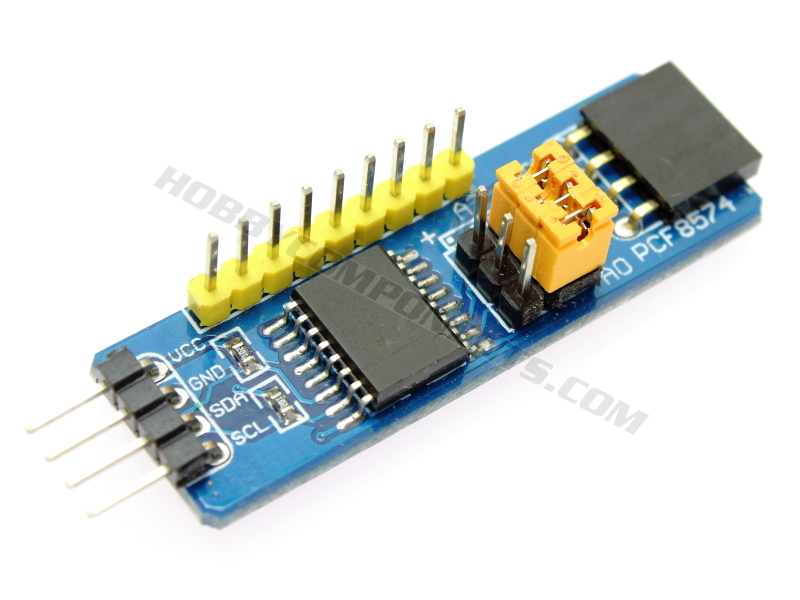
This module (HCMODU0120) is a breakout board for the PCF8574 8-bit input/output (I/O) expander IC. Using this module you can expand the available digital I/O pins of your microcontroller via its serial I2C interface. The device features an 8-bit quasi-bidirectional I/O port (P0–P7), including latched outputs with high current drive capability for directly driving LEDs. Each quasi-bidirectional I/O can be used as an input or output without the use of a data-direction control signal.

3 On-board jumpers allow selection of up to 8x I2C addresses meaning that up to 8 modules (64 I/O pins) can be connected to same I2C interface. The module also features convenient input and output headers at each end so that additional modules can simply be daisy-chained without the need for additional wires etc.

If you intend to use this module with a standard Arduino board please don't forget to download our exclusive HCPCF8574 library and example sketches which are fully compatible with this module. The library can be downloaded from the software section of our support forum here:

Note: Modules are shipped with either PCF8574T or PCF8574AT part fitted. These parts have identical operation but have a different I2C address range:

PCF8574T = 0x20 to 0x27
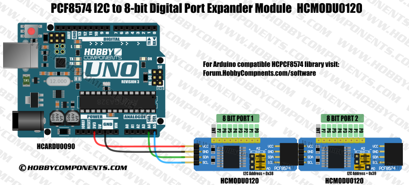
PCF8574AT = 0x38 to 0x3F


Image Image


Image


Image


Product code: HCMODU0120
2.5V to 6V VCC operation
Low Standby-Current Consumption of 10 μA Max
I2C to 8-bit Parallel-Port Expander
Open-Drain Interrupt Output
Compatible With Most Microcontrollers
Latched Outputs With High-Current Drive Capability for Directly Driving LEDs
Latch-Up Performance Exceeds 100 mA Per JESD 78, Class II


Image

1....VCC: 3.3V or 5V power supply
2....GND: Power ground
3....SDA: I2C Data
4....SCL: I2C Clock


Image

Code: Select all

/* FILE:    HCPCF8574_Blink_Example.cpp
   DATE:    24/05/17
   VERSION: 0.1
   AUTHOR:  Andrew Davies
   
24/05/17 version 0.1: Original version

This example sketch uses the HCPCF8574 library to toggle one of the PCF8574's digital pins
emulating the standard Arduino 'blink' sketch. This sketch has been written specifically for
the Hobby Components PCF8574 I2C to 8-bit digital port expander (HCMODU0120). To use the 
sketch change the I2C_ADD to match the address of your device (default is 0x38 for HCMODU0120)
and connect and LED (via a current limiting resistor) to the PCF8574's digital pin 0 (marked
D0 on HCMODU0120). You can connect your Arduino to the module as follows:

UNO/NANO........HCMODU0120
VCC.............5V
GND.............GND
A4..............SDA
A5..............SCL

More information about the library can be found in the software section of our support 
forum here:

[url]https://forum.hobbycomponents.com/software[/url]


You may copy, alter and reuse this code in any way you like, but please leave
reference to HobbyComponents.com in your comments if you redistribute this code.
This software may not be used directly for the purpose of selling products that
directly compete with Hobby Components Ltd's own range of products.
THIS SOFTWARE IS PROVIDED "AS IS". HOBBY COMPONENTS MAKES NO WARRANTIES, WHETHER
EXPRESS, IMPLIED OR STATUTORY, INCLUDING, BUT NOT LIMITED TO, IMPLIED WARRANTIES OF
MERCHANTABILITY AND FITNESS FOR A PARTICULAR PURPOSE, ACCURACY OR LACK OF NEGLIGENCE.
HOBBY COMPONENTS SHALL NOT, IN ANY CIRCUMSTANCES, BE LIABLE FOR ANY DAMAGES,
INCLUDING, BUT NOT LIMITED TO, SPECIAL, INCIDENTAL OR CONSEQUENTIAL DAMAGES FOR ANY
REASON WHATSOEVER.
*/


#include "HCPCF8574.h"    //Include the HCPCF8574 library

#define I2C_ADD 0x38      //I2C address of the PCF8574. Note parts marked PCF8574T start at address 0x20, parts marked with PCF8574AT start at 0x3F.

HCPCF8574 Port(I2C_ADD);  //Create an instance of the library


void setup() 
{
  Port.init();            //Initiliase the PCF8574 (all pins are set to high)

  Port.pinMode(0, OUTPUT); //Set digital pin 0 to an ouput
}


void loop() 
{
  Port.pinWrite(0, HIGH); //Set digital pin 0 high
  delay(1000);            //Wait 1 second
  Port.pinWrite(0, LOW);  //Set digital pin 0 low
  delay(1000);            //Wait another second
}


Image

HCPCF8574 Arduino library for the above sketch is available for download from the software section of our support forum here:

viewtopic.php?f=58&t=2190


Diagrams, libraries, and example code are provided as an additional free service by Hobby Components and are not sold as part of this product. We do not provide any guarantees or warranties as to their accuracy or fitness for purpose.

Descriptions and diagrams on this page are copyright Hobby Components Ltd and may not be reproduced without permission.

Peter1956
Posts: 3
Joined: Wed Sep 27, 2017 2:57 pm

Re: PCF8574 I2C to 8-bit digital port expander (HCMODU0120)

Post by Peter1956 » Wed Oct 11, 2017 1:20 pm

I received 3 of these and tested them, there Hex Address start at 0x20 for the current devices which are PCF8574T.
if the chip is PCF8574A the start Address is 0x38
the Sketch will need to be altered accordingly.

I.E #define I2C_ADD 0x20
Last edited by Peter1956 on Wed Oct 11, 2017 2:56 pm, edited 1 time in total.

andrew
Site Admin
Posts: 1374
Joined: Sun Aug 05, 2012 4:15 pm

Re: PCF8574 I2C to 8-bit digital port expander (HCMODU0120)

Post by andrew » Wed Oct 11, 2017 2:52 pm

Thanks for pointing this out. I've just checked and our current stock has indeed been shipped with the PCF8574 and not the PCF8574A (I believe the T just indicates the package type, i.e. SO16 so can be ignored). The only difference between the PCF8574 and the PCF8574A is as you have pointed out, their I2C address range:

PCF8574(T) = 0x20 to 0x27
PCF8574A(T) = 0x38 to 0x3F

I'll get the first post updated with this information. Sorry for any confusion caused.
Comments made by this poster do not necessarily reflect the views of Hobby Components Ltd.

Paul van de Veen
Posts: 8
Joined: Tue Oct 31, 2017 4:32 pm

Re: PCF8574 I2C to 8-bit digital port expander (HCMODU0120)

Post by Paul van de Veen » Tue Oct 31, 2017 6:12 pm

Peter1956 wrote:I received 3 of these and tested them, there Hex Address start at 0x20 for the current devices which are PCF8574T.
if the chip is PCF8574A the start Address is 0x38
the Sketch will need to be altered accordingly.

I.E #define I2C_ADD 0x20
I can't find the library. Could you post a working link please?

Thanks in advance!

andrew
Site Admin
Posts: 1374
Joined: Sun Aug 05, 2012 4:15 pm

Re: PCF8574 I2C to 8-bit digital port expander (HCMODU0120)

Post by andrew » Tue Oct 31, 2017 7:30 pm

I've fixed this link, it now points to the appropriate thread in the software section of the forum.
Comments made by this poster do not necessarily reflect the views of Hobby Components Ltd.

Paul van de Veen
Posts: 8
Joined: Tue Oct 31, 2017 4:32 pm

Re: PCF8574 I2C to 8-bit digital port expander (HCMODU0120)

Post by Paul van de Veen » Wed Nov 01, 2017 12:12 pm

Many thanks. I got it!

Paul van de Veen
Posts: 8
Joined: Tue Oct 31, 2017 4:32 pm

Re: PCF8574 I2C to 8-bit digital port expander (HCMODU0120)

Post by Paul van de Veen » Sat Nov 25, 2017 11:24 am

Hi all,
I have a problem with the PCF8574 port expander I can not explain.
2 led's are connected by means of 330Ohm resistor to Vcc and to pin0 and pin1. They are supposed to blink simultaneously.
The code is of maximum simplicity.
When I define the Port.pinMode in increasing order it works.
Port.pinMode(0, OUTPUT);
Port.pinMode(1, OUTPUT);

When I reverse toe order, it does not work. Why??
Port.pinMode(1, OUTPUT);
Port.pinMode(0, OUTPUT);

andrew
Site Admin
Posts: 1374
Joined: Sun Aug 05, 2012 4:15 pm

Re: PCF8574 I2C to 8-bit digital port expander (HCMODU0120)

Post by andrew » Sat Nov 25, 2017 5:48 pm

I can't check the library right now but looking at your posted example code are you trying to set the pins to outputs or change their logic states? If your trying to do latter then shouldn't you be using pinWrite() instead of the pinMode()?
Comments made by this poster do not necessarily reflect the views of Hobby Components Ltd.

Paul van de Veen
Posts: 8
Joined: Tue Oct 31, 2017 4:32 pm

Re: PCF8574 I2C to 8-bit digital port expander (HCMODU0120)

Post by Paul van de Veen » Sat Nov 25, 2017 6:23 pm

I am just blinking two leds as a demonstration of this phenomenon.
My code:
My code:

#include "HCPCF8574.h" //Include the HCPCF8574 library
byte I2C_ADD = 0x20; //I2C address of the PCF8574
HCPCF8574 Port(I2C_ADD); //Create an instance of the library

int PortLedpinA = 0;
int PortLedpinB = 1;

void setup()
{
Port.init(); //Initialize the PCF8574 (all pins are set to high)
Port.pinMode(PortLedpinA, OUTPUT); //Set digital pin PortLedpin1 to an output
Port.pinMode(PortLedpinB, OUTPUT); //Set digital pin PortLedpin1 to an output
}

void loop()
{
Port.pinWrite(PortLedpinA, HIGH);
Port.pinWrite(PortLedpinB, HIGH);
delay(150);
Port.pinWrite(PortLedpinA, LOW);
Port.pinWrite(PortLedpinB, LOW);
delay(150);
}


This works. Of course. You can even change PortLedpinA into 0 and PortLedpinB into 1 in all lines.

But if I change the order by changing my declarations in:
int PortLedpinA = 1;
int PortLedpinB = 0;
It does not longer work because Port.pinMode(1, OUTPUT); is called before Port.pinMode(0, OUTPUT);

andrew
Site Admin
Posts: 1374
Joined: Sun Aug 05, 2012 4:15 pm

Re: PCF8574 I2C to 8-bit digital port expander (HCMODU0120)

Post by andrew » Sun Nov 26, 2017 9:13 am

Thanks for posting the example code. I've taken a look at the library but I can't see any obvious reason why the order would make a difference. I'll set one up on Monday when I'm back in the office to see if I can replicate the issue.
Comments made by this poster do not necessarily reflect the views of Hobby Components Ltd.

Post Reply

Return to “Interface”