Prototyping adapter for ESP-07, ESP-08, ESP-12 (HCPROT0087)

Espressif Systems ESP8266 wireless microcontroller (Wifi) development boards and accessories
Post Reply
admin
Site Admin
Posts: 865
Joined: Sun Aug 05, 2012 4:02 pm

Prototyping adapter for ESP-07, ESP-08, ESP-12 (HCPROT0087)

Post by admin » Wed Oct 05, 2016 1:31 pm

Image


This adapter board is designed specifically for the ESP8266 ESP-07, ESP-08 and ESP-12 2.4GHz WiFi modules. It provides an easy way to break-out the individual pins on these modules to a standard 0.1" pitch set of headers, which are also supplied with the adapter. The adapter has a set of tinned pads which are perfectly positioned so that your ESP module can be soldered on to the adapter. Once soldered the adapter provides access to all the power, digital, analogue, and control pins. Additionally it also includes 2 pull-up/down resistors that pull the CH_PD/EN pin high and the GPIO15 pin low. This configures the attached module into the default operating mode.


Image


Specifications:

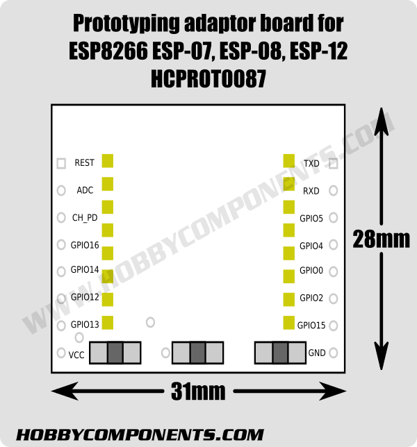
Item code: HCPROT0087
Compatible with: ESP-07, ESP-08 & ESP-12 modules
Width: 33mm
Height 28mm
Includes standard 0.1" pitch headers (not soldered)


Disclaimer: Libraries, example code, and diagrams are provided as an additional free service by Hobby Components and are not sold as part of this product. We do not provide any guarantees or warranties as to their accuracy or fitness for purpose.

Descriptions and diagrams on this page are copyright Hobby Components Ltd and may not be reproduced without permission.

Zed Eighty
Posts: 6
Joined: Sun Aug 02, 2020 10:29 am

Soldering Technique

Post by Zed Eighty » Sun Aug 02, 2020 10:40 am

Does anyone have any tips on the best technique to use to solder an ESP8266 module to this adapter board?

andrew
Site Admin
Posts: 1374
Joined: Sun Aug 05, 2012 4:15 pm

Re: Prototyping adapter for ESP-07, ESP-08, ESP-12 (HCPROT0087)

Post by andrew » Mon Aug 03, 2020 1:02 pm

I'm going to assume that you're new to soldering with this comment but the main thing to note about soldering is that solder wants to flow to a hot surface and won't flow on to a cold pad. So the technique for soldering is to use the tip of the iron to heat the pad and then whilst keeping the tip pressed against the pad, apply the solder to the pad. The other thing to note is to not to keep the iron on a pad for anything longer than a few seconds as it will overheat the pad and cause it to come loose from the PCB.

With regards to soldering an ESP module to the breakout board, my recommended technique would be first to apply some solder to one of the corner pads of the breakout board. Then hold the ESP module in the correct position and reheat the solder so that it solders the pad of the ESP module to the breakout boards pad. Let the solder cool and that should be enough to hold the module in place. If the ESP module is not lined up properly you can always just reheat the pad and adjust the position of the module. Once you're happy with it you can then solder the pad in the opposite corner. The rest of the pads can then be easily soldered in sequence.
Comments made by this poster do not necessarily reflect the views of Hobby Components Ltd.

Zed Eighty
Posts: 6
Joined: Sun Aug 02, 2020 10:29 am

Re: Prototyping adapter for ESP-07, ESP-08, ESP-12 (HCPROT0087)

Post by Zed Eighty » Mon Aug 03, 2020 2:04 pm

Many thanks Andrew, that is very helpful. Although I'm not new to soldering, I am new to working with surface mount modules and wanted to ensure I approached it with good technique before I cooked anything to destruction.

Post Reply

Return to “ESP8266”