Hobby Components 8x8x8 Cube Kit (HCKITS0050)

Hobby Component self build kits
Post Reply
admin
Site Admin
Posts: 865
Joined: Sun Aug 05, 2012 4:02 pm

Hobby Components 8x8x8 Cube Kit (HCKITS0050)

Post by admin » Wed Mar 16, 2016 10:14 am

Image


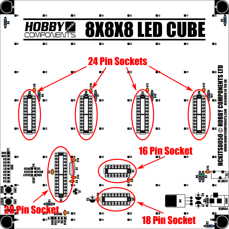
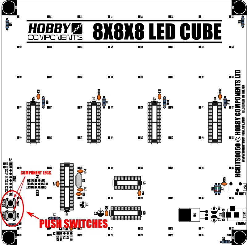
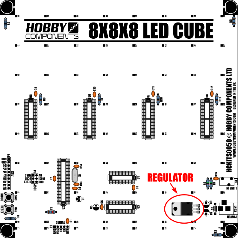
LED light cubes are a hugely popular and fun project. With this kit (HCKITS0050) you will have all the parts to build your very own. The kit includes all the components necessary to build the driver base board and a whopping 512 3mm diffused blue LEDs to build an 8 x 8 x 8 cube measuring approximately 17cm square. The kit has been deliberately designed to only use through hole components to make it as easy as possible for people who don't have much soldering experience (we do still recommend a little experience with soldering).

When completed simply plug in a power supply and the cube will spring into life displaying cool patterns in 3D - no computer is required! What's more, your completed cube is actually an Arduino compatible in disguise. It has an ATMega328 device with the Arduino bootloader pre-programmed into it. Just connect a standard programming cable and download our 8x8x8 Cube library (link below) and you can reprogram your cube with your own patterns directly from the Arduino development environment.

Please note: To construct this kit you will need a soldering iron, solder and some tools such as a pair of snips, and long nose pliers.

Please see posts 2 and 3 for a guide on how to build your LED cube kit.


Item number: HCKITS0050
Number of LEDs: 512
PCB size: 185mm x 185mm
Approx cube size (W x L x H): 170mm x 175mm x 185mm
Supply voltage (via DC input): 7.5 - 9V DC
Supply voltage (via Vcc pin): 5 - 5.5V DC
Supply current (all LEDs on): ~630mA


NOTICE: Some cube kits between shipped between the dates Nov 2018 and Jan 2019 contain a faulty IC (IC U3 - MP54562P). If your completed kit has one or more *complete* layers not working then please check the batch code etched on this IC. If the batch code is 15210 then please email use at: sales [at] hobbycomponents.com.


Image


Image

The HC8x8x8Cube library can be downloaded from the software section of this forum here:

http://forum.hobbycomponents.com/viewto ... =58&t=1968


FAQ:

How to I reprogram the cube?

To reprogram the cube you will need to have a copy of, and be familiar with the Arduino IDE which is available for free download via arduino.cc. Connect the cube to your computer via the supplied serial cable as follows:

Image

An Arduino library and example sketches are available for download via the software section of this forum here: http://forum.hobbycomponents.com/viewto ... =58&t=1968

When programming the cube via the Arduino IDE select "Arduino Nano" as the board type. If using the supplied serial cable you will also need to manually reset the cube when the sketch is uploaded. To do this reset the cube via its reset button as soon as the Arduino IDE finishes compiling your sketch and reports that it is "Uploading" it to the cube.

WINDOWS 8/VISTA/10 USERS:

The latest Prolific of the drivers for the supplied cable breaks compatibility with newer version of windows. If you have problems getting the driver to work please see the forum post for this cable for a solution.

http://forum.hobbycomponents.com/viewto ... =79&t=1815


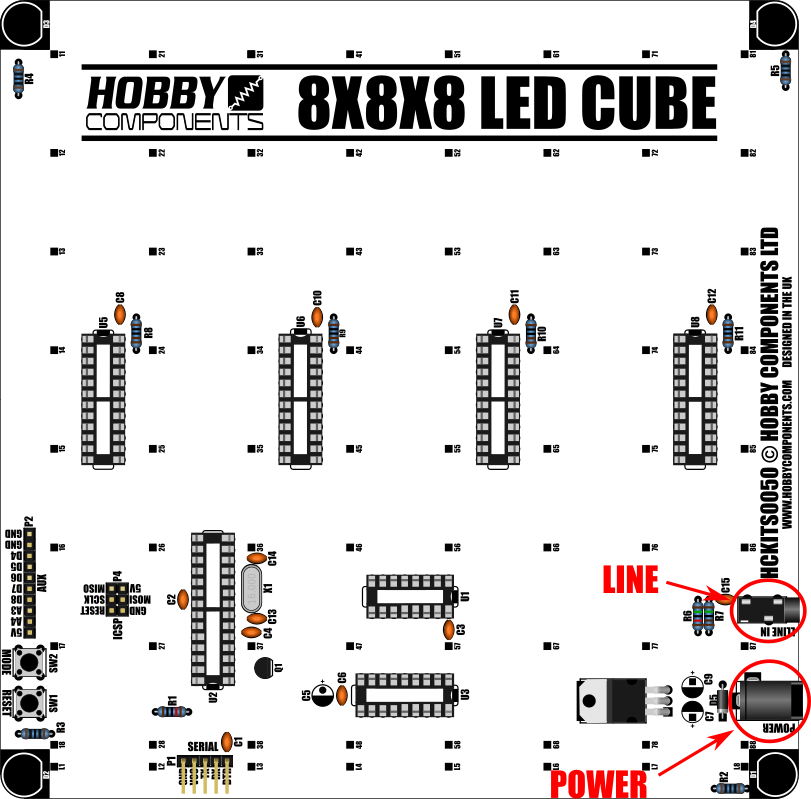
What is the purpose of the line in jack socket?

Currently this interface has no purpose which is why we don't currently advertise it as a feature. The line input would allow you to feed an analogue audio signal into analogue pin A5 of the microcontroller. This can be read using the built-in Arduino analogRead(A5) function should you wish to write your own sketches for it. If you don't plan to reprogram your cube with your own sketches then you do not have to fit the line-in components.


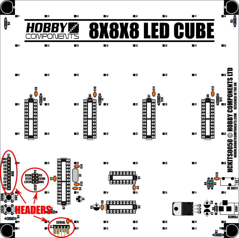
What is the purpose of the 10 pin auxiliary header?

The 10 pin auxiliary header is just a header with all the spare unused IO pins from the ATMega328. They are just brought out to the header simply to make these pins easy to access should you wish to re-program the cube and want to interface to external hardware. If you don't plan to reprogram your cube with your own sketches then you do not have to fit the auxiliary header.


Should me kit have come with a DC power cable and if not how do I power it?

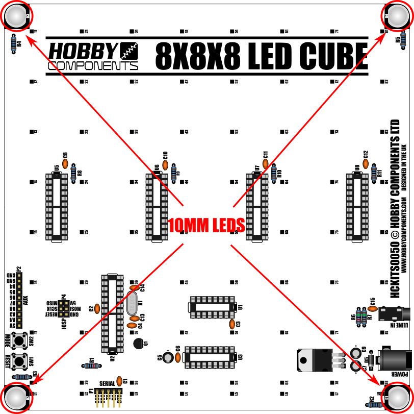
The kit doesn't come with a DC cable however it does come with a USB programming lead. You can use this cable to power your cube via a USB port on a computer or a standard 5V USB charger adapter with at least 500mA supply capability. See the image above for details of how to connect the cable. If you just wish to power the cube you only need to connect the +5V and GND wires.


I want to power the cube via the DC socket, what type of adapter to I need?

If you want to power the cube via the DC socket you'll need a DC adapter that can supply between 7.5 and 9V with a current capacity of at least 500mA. The adapter will need to have a 2.1mm DC plug supplying the +Ve to the center pin.


Image
HCKITS0050_Schematic.gif


Customer projects:

User bluethunder22 has kindly uploaded his cube build project to Thingiverse. The project includes a custom 3D printed case which also incorporates a vacuum florescent clock in the base. You can find more information including files for the 3D printed case and YouTube videos here:

https://www.thingiverse.com/thing:3696884


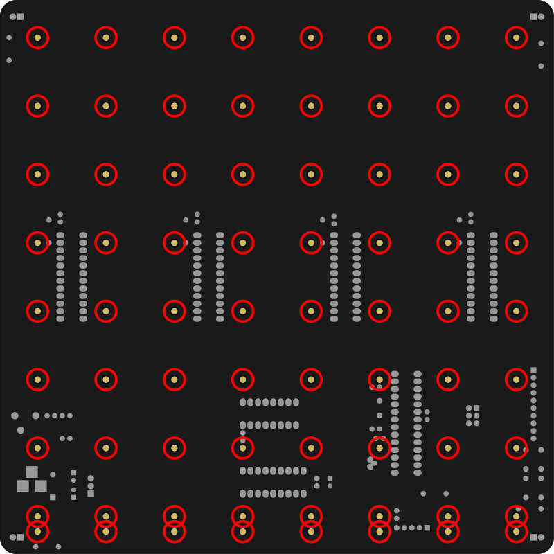
Customer David Godwin has kindly provided a template drawing for making a full sized 8x8 LED jig. The file is in DXF format:

8x8_LED_Jig_CC1.jpg
8x8 led grid.dxf
You do not have the required permissions to view the files attached to this post.

admin
Site Admin
Posts: 865
Joined: Sun Aug 05, 2012 4:02 pm

Re: Hobby Components 8x8x8 Cube Kit (HCKITS0050)

Post by admin » Wed Mar 16, 2016 11:07 am

BUILDING YOUR LED CUBE KIT PART 1 - PCB

Required Tools:
Soldering iron.
Solder.
A pair of snips for trimming component legs.
A pair of small long nose pliers for bending legs of the 3mm LEDs that make up the cube.

Recommended Tools:
A magnifying glass to help with soldering components.
A piece of perspex or plywood measuring about 185 x 185 mm which will be used as a jig for soldering the LED's that make up the cube.
3mm drill bit and drill.


Soldering tip: When soldering components to a circuit board it is always best to start with the smallest components first. This helps keep the board flat and stops access to pads from being restricted by larger components. The first step is to start by soldering the small components such as the resistors, capacitors, and diode. When soldering the components with multiple pins, such as ICs, it is recommended to solder the two opposite corner pins first. You can then check that the component is flat and if not just heat one of the soldered pads and gently push the component against the PCB to make it flat. Once you've determined that the component is flat against the PCB the other pads can be soldered.


Important notes:

For some components the orientation of the component is important. These components will be highlighted in the build guide.

When constructing the PCB, with the exception of the cube socket pins, all components should be fitted to the underside (silkscreen side) of the PCB.


Building your PCB


RESISTORS

All resistors in the kit are coloured light blue and will have a series of five coloured bands. The band colours signify the value of the resistor. When fitting these resistors the orientation of the resistor is not important.


Image

Solder the four 100 Ohm resistors (Brown, Black, Black, Black, Brown) to footprints R2, R3, R4, & R5.

Solder the four 1K Ohm resistors (Brown, Black, Black, Brown, Brown) to footprints R8, R9, R10, & R11.

Solder the one 10K Ohm resistor (Brown, Black, Black, Red, Brown) to footprint R1.


For kit versions 1.1 onwards please skip this step

For optional line input:

Solder the 1.5K resistor (Brown, Green, Black, Brown, Brown) to footprint R7.

Solder the 15K resistor (Brown, Green, Back, Red, Brown) to footprint R6.


Use a pair of snips to trim any excess component legs protruding from the opposite side of the PCB.


CAPACITORS - CERAMIC

All the ceramic capacitors in this kit are a small light brown coloured disc shape. A number on the side of the capacitor can be used to determine its value. When fitting these capacitors the orientation is not important.

Image

Solder the two 22pF (usually marked with the number 22) capacitors to footprints C13 & C14.

Solder the nine 100nF (usually marked with the number 104) capacitors to footprints C1, C2, C3, C4, C6, C8, C10, C11, & C12.


For kit versions 1.1 onwards please skip this step
For optional line input:

Solder the 10nF capacitor to footprint C15.

Use a pair of snips to trim any excess component legs protruding from the opposite side of the PCB.


16MHZ CRYSTAL

The crystal is an oval silver metal can with the number 16.000 engraved on the top. When fitting the crystal the orientation is not important.

Image

Solder the crystal to footprint X1 and use a pair of snips to trim any excess component legs protruding from the opposite side of the PCB.


Diode

The diode is a small black cylindrical component with a silver band at one end. The band denotes the negative end (cathode) of the component. When placing the diode make sure that the silver band faces the bottom of the PCB as shown in the image below.


Image

Solder the diode to footprint D5 and use a pair of snips to trim any excess component legs protruding from the opposite side of the PCB.


IC SOCKETS

IC sockets are holders that the IC's will be inserted into. There are a total of seven IC sockets to be soldered in this kit. When installing the sockets there is a small notch at one end. Each socket should be orientated so that this notch is on the same end as the white silkscreen tab on the footprint.

Image

Solder the 16 pin IC socket to footprint U1.

Solder the 18 pin IC socket to footprint U3.

Solder the 24 pin IC sockets to footprints U5, U6, U7, & U8.

Solder the 28 pin IC socket to footprint U2. Note that this socket is placed in the opposite orientation to sockets U5, U6, U7, & U8.


PUSH SWITCHES

There are two small push buttons in the kit which are used as reset and mode select buttons. They are small square silver and black components with four legs. The orientation of these switches is important. Position both switches so that the orientation of the legs matches the diagram below.

Image


Solder the push switches to footprints SW1 & SW2.


REGULATOR

Before fitting the regulator its pins need to be bent so that the regulator sits flat to the PCB. Do this by bending the pins about half way down using a pair of long nose pliers so that when the regulator is inserted into the PCB the metal tab at the top of the regulator lays flat against the heatsink pad.

Image

Solder the regulator to footprint U4 and use a pair of snips to trim any excess component legs protruding from the opposite side of the PCB. You can also optionally solder the tab of the regulator to the large square pad beneath it.


HEADER PINS

There are three headers in the cube kit, a 5 pin right angled header for the serial interface, 2 x 3 pin straight headers that make up the 6 pin ICSP header and an optional 10 pin straight header for the auxiliary interface. For the ICSP and auxiliary headers these may be provided in the kit as one continuous strip of pins. You can simply snap this strip into appropriate lengths using a pair of long nose pliers.

Image

Solder the 5 pin right angled header to footprint P1.

Optionally solder the two 3 pin header pins to footprint P4.

Optionally solder the 10 pin header to footprint P2.


TRANSISTOR

The transistor is a small black 3 pin component and will have the number BS170 etched on the flat face. The orientation of this device is important. When placing the transistor make sure that the flat face is facing in the same direction as the footprint outline.

Image

Solder the transistor to footprint Q1 and use a pair of snips to trim any excess component legs protruding from the opposite side of the PCB.


POWER AND LINE CONNECTORS

The power and optional line-in (V1.0 only) connectors are black plastic 3 pin sockets and should be positioned so that the socket is facing the outside of the PCB.

Image

Solder the 3.1mm DC socket to the footprint labelled 'POWER'.

For kit versions 1.1 onwards please skip this step
Solder the 3.5mm jack socket to the footprint labelled 'LINE IN'.


CAPACITORS - ELECTROLYTIC

The 100uF electrolytic capacitors are two legged cylindrical shaped components. These are black or dark blue with a silver stripe down one side. This stripe denotes the negative side of the component. Unlike the ceramic capacitors the orientation of these components is important. When placing the component the silver stripe on the capacitor should be on the black (V1.0 kit) or white (V1.1 kit) half of the footprint.

Image


Solder the three electrolytic capacitors to footprints C5, C7, C9 and use a pair of snips to trim any excess component legs protruding from the opposite side of the PCB.


LED CUBE SOCKETS

The LED cube sockets are provided in the kit as strips of 40 way plastic turned-pin sockets. They have round pins on one side and sockets on the other. The pins will be soldered into the PCB and the sockets are what the component legs at the base of the LED will be pushed into. Break these 40 way strips into single way pieces using the long nose pliers. When breaking them and soldering them into the PCB be careful not to bend the pins as they break easily. We have provided spare pins in the kit. You will need 72 pins in total. These single pins must be soldered to the BLACK side of the PCB (opposite side to the components). It is also important for these pins to be soldered flat to the PCB otherwise your LED cube will not sit evenly in the sockets.

Image

Solder the 72 cube sockets to the pads marked in the above image.


10MM LEDS

The four 10mm white LEDs will act as the legs of the cube. The orientation of these LEDs is important. You can identify the negative pin (cathode) as it is slightly shorter than the positive (anode) one. When placing the LED the shorter negative pin should be positioned to the flat edge on the PCB footprint.

Please note for V1.1 kit there is an error in the silkscreen - for this version of kit orientate the LEDs so that the short negative leg is inserted into the the footprints square pad and the positive long leg is inserted into the footprints round pad.


Image

Solder the 10mm LEDs to footprints D1, D2, D3, & D4 and use a pair of snips to trim any excess component legs protruding from the opposite side of the PCB.


INSERT THE ICs

All the components that require soldering should now be soldered to the PCB. The final step is to insert the ICs into the IC sockets. The orientation of the ICs is important. At one end of each IC there will be either a notch or a small circle cut into the IC package. When inserting the ICs make sure they are orientated so that this end is at the same end as the silkscreen tab on the footprint.

Image

Insert the 16 pin IC into the U1 socket.

Insert the 18 pin IC into the U3 socket.

Insert the 28 pin IC into the U2 socket. Note that this IC is placed in the opposite orientation to IC's U5, U6, U7, & U8.

Insert the four 24 pin ICs into sockets U5, U6, U7, & U8.


This completes the building of the PCB. You can now proceed to constructing the LED cube.

The contents of this guide are copyright Hobby Components Ltd and may not be copied, reproduced, or reused elsewhere without permission.

admin
Site Admin
Posts: 865
Joined: Sun Aug 05, 2012 4:02 pm

Re: Hobby Components 8x8x8 Cube Kit (HCKITS0050)

Post by admin » Fri Mar 18, 2016 10:40 am

BUILDING YOUR LED CUBE KIT PART 2 - THE CUBE

To build your LED cube you will need to solder the 512 LEDs supplied in your kit in to 8 sets of 8 x 8 grids. This will take a little time and so it is important that you understand how to construct these grids before starting.


Step 1:

Note: When bending the legs of the LEDs be careful not to cause too much mechanical stress to the base of the LED as this can damage them in a way where they will either no longer work, or work intermittently. We recommend using long nose pliers when bending the legs at the base. We also provide extra LEDs in the kit just in case of accidental damage.


Image

The LED cube is made by constructing 8 sets of 8x8 LED grids and then soldering each grid together to make the full 8x8x8 cube. You can use the template supplied with the kit to make each 8x8 grid. First make sure the template is orientated as above and then place a 3mm LED into each of the 16 holes. Position each LED so that the short leg of each LED is on the left and the long leg is on the right.


Step 2:

Image

Next, bend the short leg of each LED 90 degrees near the base of the LED so that it points towards you. The short legs of the LEDs on the top row should be touching the short legs of the LEDs on the second row.


Image


Now solder each short leg of the top row LEDs to the short leg of the bottom row LEDs.


Step 3:

Image

Next, bend the long leg of each LED 90 degrees to the right so that each leg touches the long leg of the LED directly to its right. Make sure you bend each long leg slightly higher than the short leg so that it can pass over the short leg of the LED to its right without touching it. Also, do not bend the long legs of the right most LEDs on both rows, leave them pointing upwards as shown in the above image.


Step 4:

Image

Now solder each long leg where it touches the long leg of the LED directly to its right. Do this for both rows.


Step 5:


Image


To add another row of 8 LEDs to the grid gently remove the two rows from the template and then insert the top row of LEDs into the bottom row of the template so that the top row of the template is now empty.

Then insert a new row of 8 LEDs into the empty top row of the template and repeat steps 2 and 3 to add the new row to the existing two rows.

Repeat this process until you have 8 rows of 8 LEDs.


Step 6:

You have now completed one 8 x 8 grid of LED's. Carefully remove this grid from your template and set it aside and repeat steps 1 to 4 to create 7 more identical grids.


Step 7:

Once you have 8 complete grids you are now ready to construct your cube.

Before proceeding it is recommended to test each grid in turn as it is inserted into the controller board.

Image
Take one of your 8x8 grids and insert the remaining short legs on the end row into the sockets on the controller board as pictured above. Be careful not to bend the sockets when inserting the legs into the sockets as the are a firm fit. Note the extra row of pins on the controller board in the far left of the picture. These are the positive supply pins and are used to supply power to each horizontal row of the LED cube. The remaining 8x8 grid are the negative pins and are tuned on and off to control each column of LEDs above it. By controlling these two sets of pins to select a particular row and column each individual LED in the cube can be selected. With your first grid inserted use a piece of wire to connect one of the positive supply pins to one of the long legs of your grid as showing in the above image. If everything is connected correctly you should see the row of LEDs flash on and off in random patterns as the controller board runs the pre-programmed demo . Do this for each row of the grid to check that there are no bad connections.


Step 8:

Image
Once you have checked all the rows of your grid repeat step 5 for each of your 7 remaining 8x8 grids. All the LEDs of each grid should be pointing in the same direction. Once all the grids have been inserted disconnect the controller board from your computer before proceeding.


Step 9:

Image
Solder the remaining unconnected long legs of each of your 8x8 grids to the legs of the next grid. Start with the top row of legs and work your way down. Before soldering make sure each 8x8 grid is evenly spaced so that the entire cube is square.

Take a look at your cube. If every LED has been soldered correctly you will notice that all the long legs on each horizontal 8x8 grid are connected together and the short legs of each 8 led column are connected together and in-turn connected to one of the negative pins of control board.


Step 10:

Image
The final step is to connect the long legs of each horizontal 8x8 grid to the positive pins on the controller board. Reference the above image for the order.
Each of 8 positive pins should be connected to one of the horizontal 8x8 grids with a piece of wire. If the wire you are using isn't insulated then you will need to make sure that it is slightly bowed out so that it doesn't touch any of the LEDs it runs past.

Your cube is now complete.

The contents of this guide is copyright Hobby Components Ltd and may not be copied, reproduced, or reused elsewhere without permission.

patmolloy
Posts: 1
Joined: Sat Sep 30, 2017 11:39 am

Re: Hobby Components 8x8x8 Cube Kit (HCKITS0050)

Post by patmolloy » Thu Oct 05, 2017 8:23 am

Fantastic kit. Built the easy part last night .. a few thoughts ..

Would it be an idea to supply the LED jig/template as part of the kit, even if it pushes the price a little ?

Getting a good result does depend on the accurate placement of the leds, and I am not sure I trust myself to do a fantastic job creating the jig/template.

I would be tempted to add a note (even though the instructions *are* clear) that the U2 chip is notch down, and is NOT the same orientation as U5,6,7,8 which are all notch up. I "assumed" (wrongly) that all of the chips would be oriented the same way .. discovered on a final check.

Congrats to whoever created this. Great fun!

Pat

andrew
Site Admin
Posts: 1374
Joined: Sun Aug 05, 2012 4:15 pm

Re: Hobby Components 8x8x8 Cube Kit (HCKITS0050)

Post by andrew » Thu Oct 05, 2017 9:39 am

Thanks! There's some very good points...
Would it be an idea to supply the LED jig/template as part of the kit, even if it pushes the price a little ?
We did think about this when designing the kit as a jig does make a big different. The main issue is because of the large size of the PCB it is by far the most expensive part in the kit. As a result adding a full size jig would have had a significant effect on the price. That said, maybe it's something we can do as an optional extra. Or even making a cut down 8x2 ruler shaped jig which would probably be enough to accurately build a grid of LEDs.
I would be tempted to add a note (even though the instructions *are* clear) that the U2 chip is notch down
Good suggestions, a note has now been added to the appropriate sections of the build guide :-)
Comments made by this poster do not necessarily reflect the views of Hobby Components Ltd.

motorwrists
Posts: 10
Joined: Sun Oct 15, 2017 5:31 pm

Re: Hobby Components 8x8x8 Cube Kit (HCKITS0050)

Post by motorwrists » Sun Oct 15, 2017 6:20 pm

Hi Hobby Components
Thanks for great kit I have everything built but I am have problems with the PCB. Would be most grateful if anyone could help me trouble shoot.
Rows L1, L2, L5 and L6 are not lighting. I have tested the LED grids on the working rows and all the LED grids are lighting up when fitted to a working row.
I have attached image showing non-working rows in pink.
Image
Cheers and thank you.

andrew
Site Admin
Posts: 1374
Joined: Sun Aug 05, 2012 4:15 pm

Re: Hobby Components 8x8x8 Cube Kit (HCKITS0050)

Post by andrew » Mon Oct 16, 2017 9:03 am

Can you swap ICs U5 with U6 and U7 with U8. Be careful when removing the ICs, you'll need to use something flat to pry them out of their sockets from both ends. Do the working and non-working columns now swap over? Also would you by any chance be powering the cube via and external 5V adapter? If so can you avoid using it for now and try the cube via a computers USB port.
Comments made by this poster do not necessarily reflect the views of Hobby Components Ltd.

motorwrists
Posts: 10
Joined: Sun Oct 15, 2017 5:31 pm

Re: Hobby Components 8x8x8 Cube Kit (HCKITS0050)

Post by motorwrists » Mon Oct 16, 2017 11:58 am

Hi Andrew, thanks for coming back. I tried swapping ICs (it was already running via USB/computer). Unfortunately same issue exists, but I notice column 57 was lighting (not as quite as bright as the working rows though).
Cheers
Graham

andrew
Site Admin
Posts: 1374
Joined: Sun Aug 05, 2012 4:15 pm

Re: Hobby Components 8x8x8 Cube Kit (HCKITS0050)

Post by andrew » Mon Oct 16, 2017 2:28 pm

Sorry, can I confirm that you are saying you swapped the ICs but other than column 57 lighting the non-working columns didn't change?

Edit: Also this is a bit of a guess but can you check the soldering of IC U1. Especially pin 2.
Comments made by this poster do not necessarily reflect the views of Hobby Components Ltd.

motorwrists
Posts: 10
Joined: Sun Oct 15, 2017 5:31 pm

Re: Hobby Components 8x8x8 Cube Kit (HCKITS0050)

Post by motorwrists » Mon Oct 16, 2017 4:12 pm

Hi, Yes, swapped ICs around, same rows failed with exception of dimmer leds on column 57. Checked IC U1, soldering looks ok. I have attached photo of U1 and column 57.
Thanks
You do not have the required permissions to view the files attached to this post.

Post Reply

Return to “Kits”