Description:
Kit of components containing everything you will need (excluding tools and solder) to build your own LED clock. The completed clock is based on that Atmel AT89S52 microcontroller and comes pre-flashed with an example clock application. This application provides a clock, date, temperature and alarm functionality. However if you want to use this display in you own application you can simply re-flash the microcontroller via the provided ICSP header. As well as a built in microcontroller the completed kit provides the following functionality:
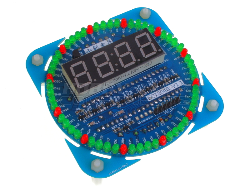
4 digit seven segment display:
Allowing the ability to display the current time, date and temperature via the included in temperature sensor.
60 LED's:
60x 3mm LED's in a novel circular arrangement mimicking a pin wheel clock. Each LED can be individually controlled via the microcontroller.
Real time clock:
DS1302 based real time clock with battery backup providing the ability for accurate time keeping.
Temperature sensor:
18B20 temperature sensor allowing accurate monitoring of current temperature.
Buzzer
Piezo buzzer which can be used as an alarm, hourly chime, or for control feedback.
Push buttons:
To push buttons (mode & plus) provide user control for settings or mode selection.
Power:
The completed board can be powered via a USB socket and supplied USB cable.
Additionally the microcontroller's serial port is made accessible in an arrangement allowing for easy interfacing to a Bluetooth module (see item HCARDU0004) or USB serial adaptor (HCARDU0011) providing the option of wireless monitoring and control via your application.
Please note that this kit requires soldering of 0603 sized components.
Build instructions:
Soldering tip: When soldering components to a circuit board it is always best to start with the smallest components first. This helps keep the board flat and stops access to pads from being restricted by larger components. The first step is to start by soldering the small surface mount resistors, capacitors, and transistors. In your kit these will be packages in paper or plastic strips and their values are marked appropriately. These components are very small and it is wise when handling and positioning them to use a small pair of tweezers. The best technique to soldering them to the board is to first apply a small amount of solder to one of the pads on the PCB. The with the component held in your tweezers, carefully position the appropriate pad of the component against the soldered pad. Then with your soldering iron heat the solder so that it sticks to the component whilst gently pushing the components against the pad. Once the component is correctly positioned allow the solder to cool by removing the iron. The component should then be attached to the PCB and in the correct position for you to easily solder the remaining pad(s).
SM resistors, capacitors, and transistors
Locate the following pads on the upper side of the PCB:
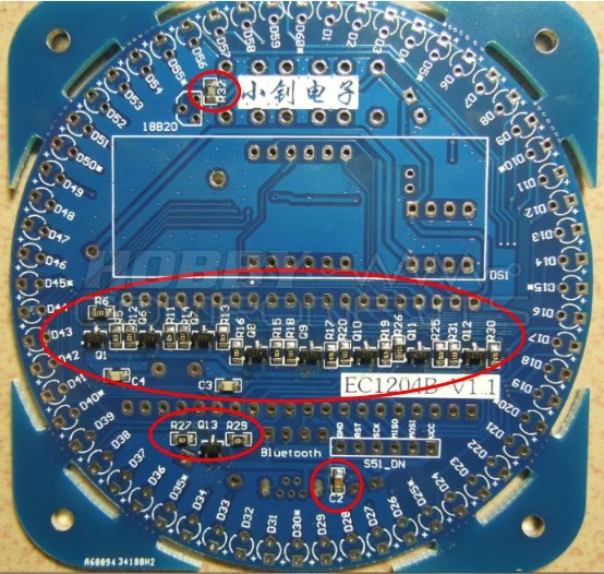
Solder the following components to the appropriate pads:
Transistors to: Q1, Q6, Q7, Q8, Q9, Q10, Q11, Q12, Q13
10K resistors to: R6, R12, R14, R16, R18, R20, R26, R29, R31, R32
47R resistors to: R5, R11, R13, R15, R17, R19, R25, R27, R30
20pF capacitors:C3, C4
0.1uF capacitor (marked 104): C2
Locate the following pads on the underside of the PCB:
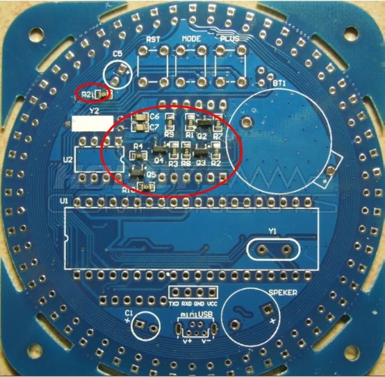
Solder the following components to the appropriate pads:
Transistors to: Q2, Q3, Q4, Q5
10K resistors to: R1, R2, R3, R4, R21
47R resistors to: R7, R8, R9, R10
20pF capacitors:C6, C7
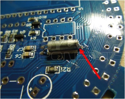
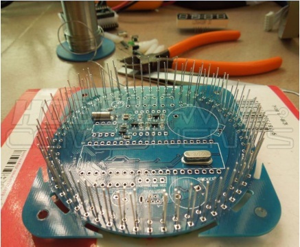
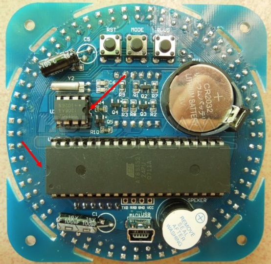
Crystals:
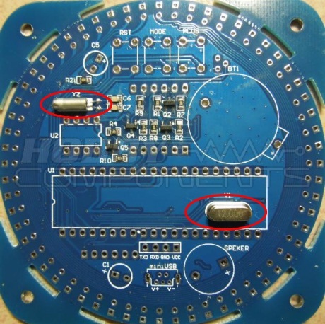
Solder the 12.000MHz and 32.762KHz crystals as shown above. For the 12.000MHz crystal make sure that it is soldered flat to the PCB as it needs to sit under the microcontroller IC. For the 32.768KHz crystal there is an additional pad that allows you to secure the end of the CAN to the PCB with solder. See image below:
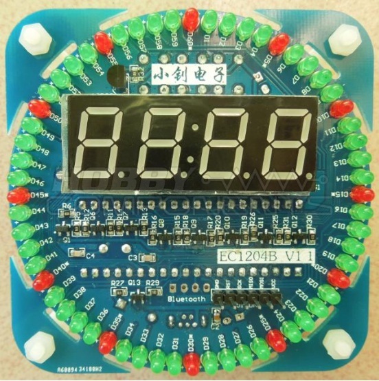
3mm LED's
Next solder the 60 red and green LED's around the edge of the PCB as shown in the following image:
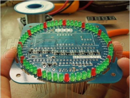
Note that pads D5*, D10*, D15*, D20*, D25*, D30*, D35*, D40*, D45*, D50*, D55*, D60* are marked with an astrix. These are for the red LED's. The rest are for the green LED's. When soldering these LED's it is important it insert these the correct way around. You will notice that there is a tiny + mark next one of the two pads for each LED on the PCB. You must insert the longest leg on the LED (the positive leg or anode) into this pad and the shorter leg (cathode) into the other pad.
Soldering tip: When soldering LED's (or similar through hole components), push the LED so that it sits flat against the PCB, then on the underside of the board splay the two legs outwards slightly. This will help hold the LED in place whilst it is being soldered. Do this for all 60 LED's then with the board sat against a flat desk, solder one leg of each LED. When you have soldered one leg of each LED check that all the LED's sit flat to the PCB then then solder the other legs.
DS18B20 Temperature sensor
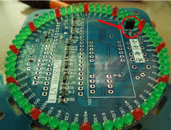
Solder this to the upper side of the PCB
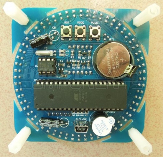
Push switches, IC sockets, capacitors, speaker and battery holder
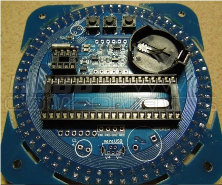
Solder the 3 push switches [RST , MODE, and PLUS), battery holder, 8 and 32 pin IC sockets to the underside of the PCB. If you wish, the 3 push buttons can be soldered to the upper side of the PCB. For the two electrolytic capacitors, unlike the surface mount versions soldered previously, these need to be oriented correctly. The negative side of these capacitors is indicated with a white stripe marked with minus symbols. This side of the capacitor must be soldered to the pads of C1 and C5 that are NOT marked with a plus sign. For the speaker this also need to be inserted into pads marked SPEAKER in the correct orientation. Make sure that the + sign on the speaker is on the same side as the PCB pad also marked with a +.
Soldering tip: For the IC sockets, solder pins on the opposite ends of the socket first. That way if your socket is not flat the pads can easily be reheated one at a time to reposition the socket. Once flat, the rest of the pins can then be soldered.
Seven segment display
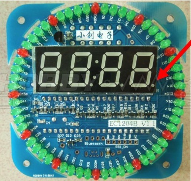
Solder the 4 digit , seven segment display to the upper side of the board. Make sure that the decimal points are to the bottom of the board. Use the soldering tip for the IC sockets to ensure that the display is flat before soldering all the pins.
6 PIN ICSP header
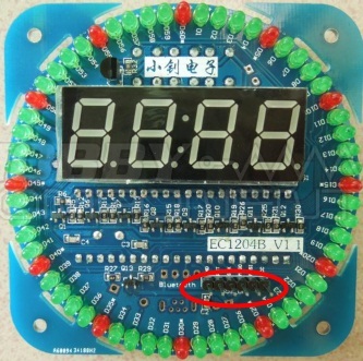
If you plan to re-flash the microcontroller with your own applications then you can solder the 6 pin header strip as shown above.
USB connector
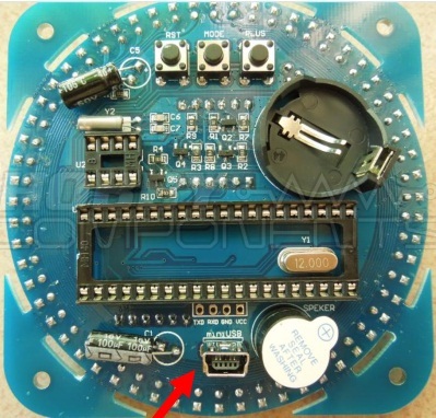
A micro USB socket and cable is provided to allow powering the board from a USB port. Solder the connector to the underside of the PCB as shown.
IC's and battery
Finally insert the two IC's, taking note of correct orientation, into the IC sockets. Insert the CR2032 battery in the battery holder with the positive side (+) facing upwards.
Commissioning:
Your kit is now complete. Give the board one final visual inspection for solder bridges, dry joints, or components inserted incorrectly before applying power. Once you are satisfied that everything is soldered correctly connect you board to a USB port with the supplied cable. The example application should now be running.
Files:
Please log in to download these files.