

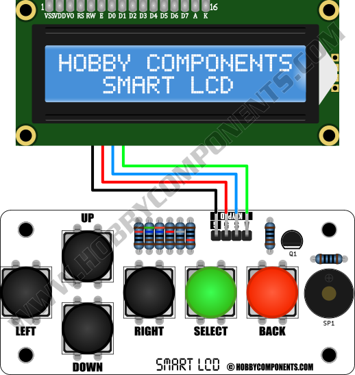
The SmartLCD Keypad Kit is an optional add-on for the Hobby Components Smart LCD (HCMODU0122). When constructed this add-on board connects to the SmartLCD's keypad header using a single 4 way cable (supplied). Once connected it adds the additional features of keypad control (up, down, left, right, select, and back) and audible output to your end application.
Access to button states and speaker output is then available via the SmartLCD's I2C or UART interfaces using its built-in commands (See the SmartLCD's manual for more information)
Features:
Product code: HCKITS0058
Connects to the Smart LCD to add keypad input and speaker output to your application - no additional pins required
Control of keypad and speaker is done through existing Smart LCD serial commands.
Adds UP, DOWN, LEFT, RIGHT, SELECT, and BACK keypad control.
Easy to solder through-hole components.
Designed to allow panel mounting.
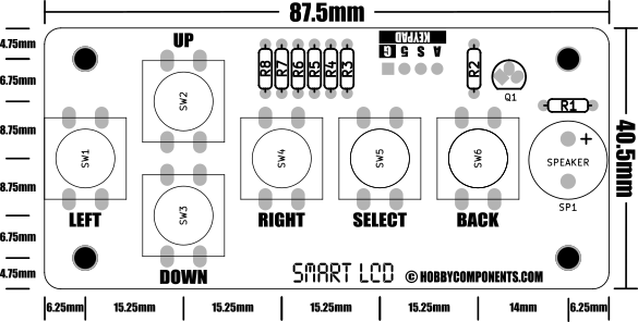
Dimensions:
Build Guide:
Resistors
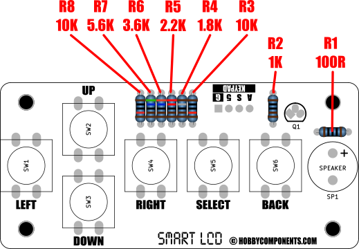
Locate the following pads on the PCB and solder the appropriate resistors in place.
R8 Resistor Value: 10K (BROWN, BLACK, BLACK, RED, BROWN)
R7 Resistor Value: 5.6K (GREEN, BLUE, BLACK, BROWN, BROWN)
R6 Resistor Value: 3.6K (ORANGE, BLUE, BLACK, BROWN, BROWN)
R5 Resistor Value: 2.2K (RED, RED, BLACK, BROWN, BROWN)
R4 Resistor Value: 1.8K (BROWN, GRAY, BLACK, BROWN, BROWN)
R3 Resistor Value: 10K (BROWN, BLACK, BLACK, RED, BROWN)
R2 Resistor Value: 1K (BROWN, BLACK, BLACK, BROWN, BROWN)
R1 Resistor Value: 100R (BROWN, BLACK, BLACK, BLACK, BROWN)
4 way R/A header pins
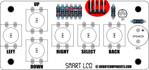
The 4 way header can be soldered to the either the upper or lower side of the PCB depending on your preference. Soldering tip - Solder just 1 pad first then check to make sure the header is flat against the PCB. If it isn't it will be easier to adjust. Once level the remaining 3 pads can be soldered.
Speaker
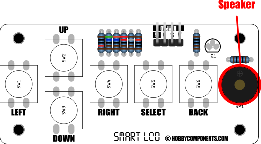
Solder the speaker to pad SP1. Note that the speaker should be orientated so that the '+' symbol on the speaker is on the same side as the '+' symbol on the PCB.
Transistor
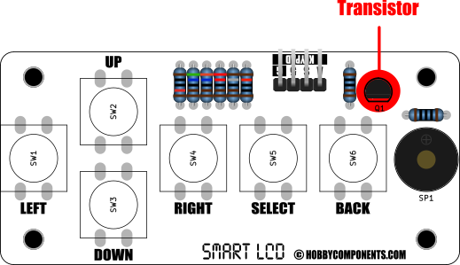
Solder the transistor to pad Q1. Note that the transistor should be orientated so that the flat side of it's case matches the flat side of its PCB symbol.
Switches
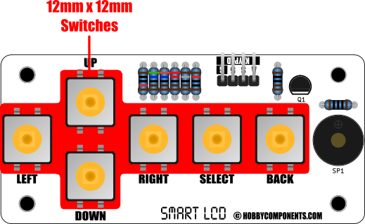
Solder the six 12mm x 12mm push switches to pads SW1, SW2, SW3, SW4, SW5, and SW6. Note the orientation of the pins in the above diagram.
Switch caps
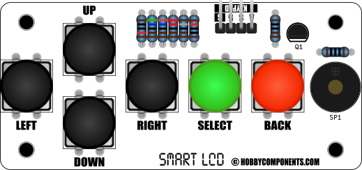
Finally, add the caps to the push buttons so that they match the above image.
Schematic:
Disclaimer: Libraries, example code, and diagrams are provided as an additional free service by Hobby Components and are not sold as part of this product. We do not provide any guarantees or warranties as to their accuracy or fitness for purpose.
Descriptions and diagrams on this page are copyright Hobby Components Ltd and may not be reproduced without permission.