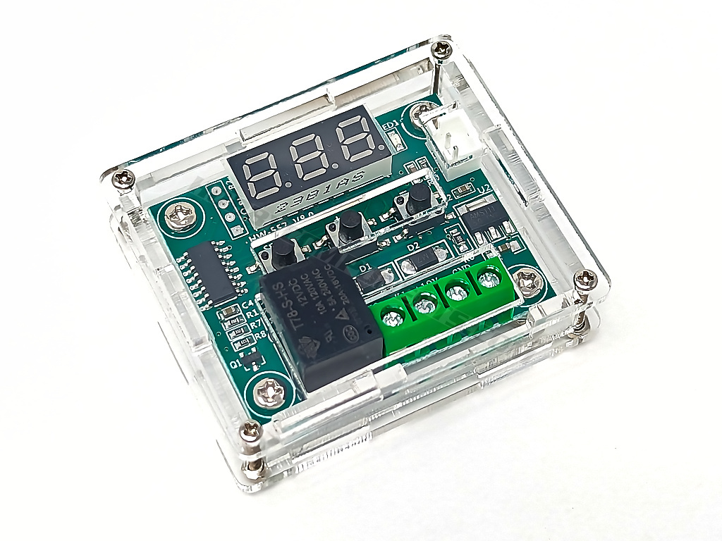

Low profile perspex case for W1209 temperature control module (see item: https://hobbycomponents.com/sensors/684 ... rol-switch).
Build guide
Tools:
A large cross-head screwdriver for M3 screws
A small cross-head screwdriver for M2 screws
A pair of long nose pliers
Please note:
Images show the case panels with protective backing for clarity purposes. The protective backing should be removed before construction.
Important:
Sometimes the standoffs may have some excess material leftover from the manufacturing process. If you find that you have trouble inserting the M3 screws into the standoffs then please check the standoff and carefully clear any excess material using a small file or craft knife. DO NOT use excessive force to insert the screws into the standoff as they may split open.
All screws should be inserted so that they are secured with nuts on the bottom side of the case. Fitting in this orientation will ensure that there is no possibility of a nut working loose and shorting the W1209 module.
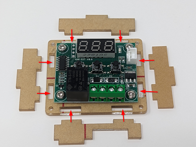
Step 1:
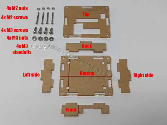
Before building the case, first identify and confirm that you have all the parts. Use the above image for reference.
Step 2:
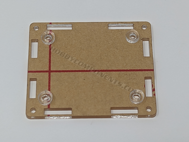
Lay the bottom case panel on a flat surface and locate the four M3 mounting holes, then lay the four standoffs on top of each hole.
Step 3:
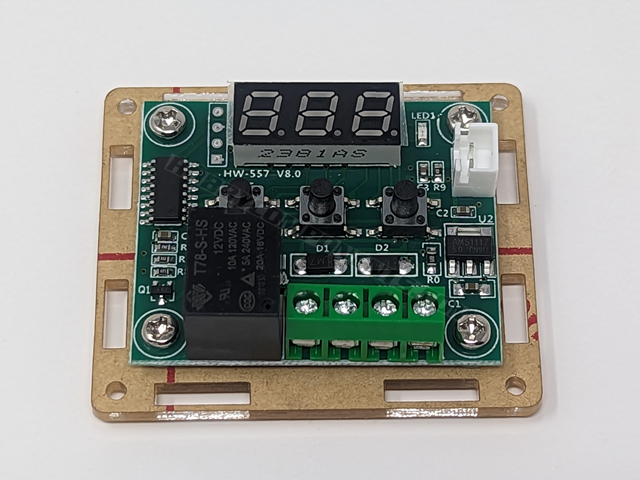
Carefully lay your W1209 module on top of the standoffs so that the mounting holes of the module line up with the holes of the standoffs.
Next, insert the four M3 screws into the modules mounting holes checking that they go through each standoff and through the M3 holes of the bottom panel. The screws should slightly protrude out the back of the bottom panel. If they do not check everything is aligned correctly.
Once the M3 screws are in place then secure them in place with the m3 nuts via the underside of the bottom panel.
Note: Sometimes the legs of through-hole components on the W1209 module may not be trimmed properly which will stop the module from sitting flush with the standoffs. This will also cause the M3 screws not to fully protrude out of the bottom of the case. If you have problems fitting the M3 nuts then remove the module and trim any excess pins with a pair of snips and repeat step 2 & 3.
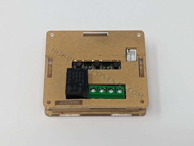
Step 4:
On a flat surface identify the left, right, top & bottom side panels and lay them out orientated as shown in the image. Note how the tabs line up with the tab slats on the bottom panel.
Step 5:
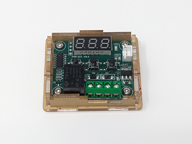
Insert each side panel into the bottom panel slots. You should be able to insert them with minimal force.
Step 6:
Place the top panel onto the top of the case. You will need to adjust the position of each side panel so that their tabs fit through the 4 slot holes of the top panel.
Step 7:
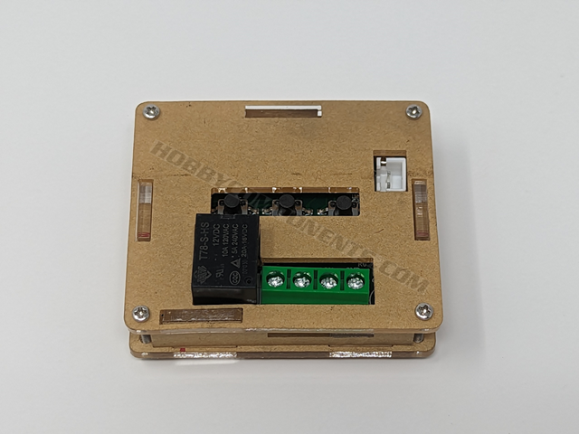
With the top panel fitted insert the four M2 screws into the M2 holes of the top panel and then through the M2 holes of the bottom panel.
Secure the M2 screws with the M2 nuts via the underside of the case.
Libraries, example code, and diagrams are provided as an additional free service by Hobby Components and are not sold as part of this product. We do not provide any guarantees or warranties as to their accuracy or fitness for purpose.
Descriptions and diagrams on this page are copyright Hobby Components Ltd and may not be reproduced without permission.