Hobby Components 16 Channel Logic Analyser (HCTEST0035)

Hobby components test equipment
Post Reply
admin
Site Admin
Posts: 865
Joined: Sun Aug 05, 2012 4:02 pm

Hobby Components 16 Channel Logic Analyser (HCTEST0035)

Post by admin » Fri Dec 07, 2018 10:46 am

Image


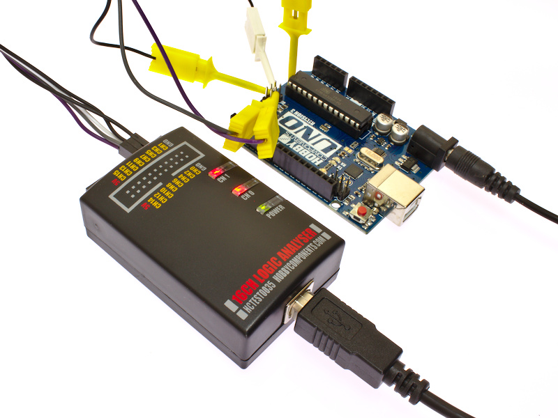
The Hobby Components logic analyser can capture up to 16 separate channels of 3.3V or 5V logic signals at a maximum sample rate of 12MS/s. Designed for use with the open source Sigrok PulseView and sigrok-cli software, this analyser is a complete low cost solution capable of capturing and decoding many popular types of serial and parallel protocols including I2C, SPI, UART, PWM, etc.


• 16 channels at up to 12MS/s*.
• Capture depth of up to 1T samples*
• Compatible with 3.3V & 5V logic levels.
• Compact design, no additional hardware required - just connect the analyser to your computer with supplied USB cable, install the software and you're ready to go.
• Compatible with Microsoft Windows 7, 8, 10 32/64 bit (other operating systems are supported).
• Works with Sigrok PulseView and sigrock-cli.


Image


Package contents include:

1 x 16 channel logic analyser device
1 x USB cable
4 x Blue Test leads
4 x Green Test leads
4 x Yellow Test leads
4 x White Test leads
2 x Black Test leads
2 x Red Test leads


* Maximum capture rate and memory depth may depend on the specification and performance of your computer system. An internet connection is required for software download.

PulseView and sigrok-cli is a separate open source cross-platform project developed by the Sigrok team. Latest builds of the software and more information about the project can be found by visiting the official Sigrok website sigrok.org.


Sigrock PulseView Software:

Real Time Clock Example:
Image

ARM ETMv3 Example:
Image

EEPROM Example:
Image

Z80 Example:
Image


Windows Users:


Sigrok software:

The latest version of the Sigrok software can be downloaded from the official Sigrok website (sigrok.org). The latest Windows build of the PulseView (GUI) software can be downloaded here:

https://sigrok.org/wiki/Downloads


Drivers:

To use your analyser with the Sigrok software you will first need to install a driver. To do this you can use the Zadig driver install utility which is downloaded with the Sigrok Pulseview software:

1) Connect your analyser to the computer using the supplied USB cable. Windows will complain that it cannot find a driver but just ignore this message.

2) After downloading and installing the Sigrok Pulseview software the Zadig utility can be found in one of the following paths:

C:\Program Files (x86)\sigrok\PulseView\

OR

C:\Program Files\sigrok\PulseView\


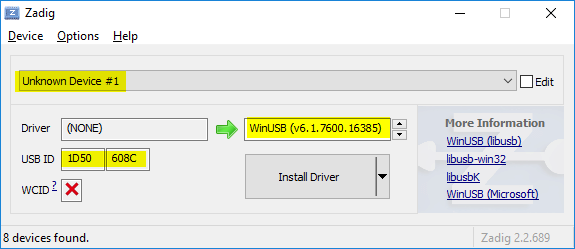
3) Run the Zadig utility by double clicking the zadig.exe executable. Note, if you are using Windows XP then run the zadig_xp version instead.

4) The Zadig utility should now open up. In the drop down box at the top of the window you should be able to select the analyser. It will normally be listed as 'Unknown Device #1'. If you don't see it listed then go to Options->List all devices and try the drop down box again. You can confirm that you have the right device selected by checking that the USB ID text box is showing the correct VID and PID (1D50 & 608C). Also make sure you have WinUSB (v6.1.xxx.xxxxx) selected for the driver version.


Image


5) Click the 'Install Driver' button. This will automatically install a driver for the analyser. You can now close the Zadig window and run the pulseview software.

6) Disconnect the analyser and reconnect it before running pulseview. In Pulseview the analyser should appear at the top of the window as 'sigrok FX2 LA (8ch)'


Libraries, example code, and diagrams are provided as an additional free service by Hobby Components and are not sold as part of this product. We do no provide any guarantees or warranties as to their accuracy or fitness for purpose.

Descriptions and diagrams on this page are copyright Hobby Components Ltd and may not be reproduced without permission.

cromarty
Posts: 1
Joined: Fri Dec 14, 2018 9:14 am

Re: Hobby Components 16 Channel Logic Analyser (HCTEST0035)

Post by cromarty » Fri Dec 14, 2018 2:06 pm

Hello. I just bought a CY7C68013A from Amazon. I am looking for examples of how to use it to analyse things like PWM signals to get the duty cycle.

Complication is I am totally blind, so I cannot see graphics and cannot identify any of the 40 pins in the two banks of 20 on each side of the board.

I have been unable to find any text descriptions of the pins, or what they are, how to use them.

I need to be able to connect at least one channel to one PWM signal and then run sigrok-cli to get the analysis.

Can somebody either do me a detailed description of the placement and function of each pin, or point me to where I can find one. Note that I will need orientation info, such as "holding the board with the USB connector at the top..." if you see what I mean.

The amount of textual 'how to' stuff here online is abysmal

andrew
Site Admin
Posts: 1374
Joined: Sun Aug 05, 2012 4:15 pm

Re: Hobby Components 16 Channel Logic Analyser (HCTEST0035)

Post by andrew » Fri Dec 14, 2018 2:20 pm

I've just replied to your direct email with an answer to this question but for convenience and for anyone else that will find this information useful i'll post it here...
If you hold the board so that the USB connector is to your left and the reset button and jumper is to your right the two sets of header pins should then run parallel to yourself.

We'll call the first row of 10 pins that's closest to you (along the edge of the board) row 1, the next one row two and then on the far side of the board the row closest to you row 3 and finally the row on the far edge of the board row 4.

Starting with row 1 and running from left to right:

The first pin, pin 1 = Channel 13
Pin 2 = Channel 15
Pin 5 = Ground
Pin 6 = Ground
Pin 8 = Channel 0
Pin 9 = Channel 2

For row 2 running from left to right:

The first pin, pin 1 = Channel 14
Pin 2 = Ground
Pin 3 = Ground
Pin 5 = Ground
Pin 8 = Channel 1
Pin 9 = Channel 3

For row 3 running from left to right:

The first pin, pin 1 = Channel 12
Pin 2 = Channel 10
Pin 3 = Channel 8
Pin 9 = Channel 7
Pin 10 = Channel 5

For row 4 running from left to right:

The first pin, pin 1 = Channel 11
Pin 2 = Channel 9
Pin 9 = Channel 6
Pin 10 = Channel 4


All other pins are not used for the logic analyser.
Comments made by this poster do not necessarily reflect the views of Hobby Components Ltd.

AndyPreston
Posts: 4
Joined: Tue May 01, 2018 12:51 pm
Location: Swindon

Re: Hobby Components 16 Channel Logic Analyser (HCTEST0035)

Post by AndyPreston » Wed Feb 12, 2020 9:09 pm

I see from your section here about drivers that this is a Cypres FX2 based analyser. But can anyone tell me what else is inside?

In Joel Holdsworth's Open Tech Lab episode about logic analysers https://opentechlab.org.uk/videos:001:notes he shows us a Chinese Saleae Logic 16 clone that as well as having the usual Cypres FX and buffer chip also has an FPGA that packs the data to achieve higher bandwidths, and I was wondering if this is a similar device.

I could find out by buying one and whipping the lid off, but I'm a tight-wad and I'd kinda like to know what I'm getting before I buy.
------------
https://gitlab.com/edgeeffect
https://www.youtube.com/user/edgeeffect

andrew
Site Admin
Posts: 1374
Joined: Sun Aug 05, 2012 4:15 pm

Re: Hobby Components 16 Channel Logic Analyser (HCTEST0035)

Post by andrew » Thu Feb 13, 2020 9:36 am

I see from your section here about drivers that this is a Cypres FX2 based analyser. But can anyone tell me what else is inside?
It does indeed use a Cypress FX2 device with the addition of two 74LCX245 transceivers to give it both 3.3V and 5V level comparability.

In Joel Holdsworth's Open Tech Lab episode about logic analysers https://opentechlab.org.uk/videos:001:notes he shows us a Chinese Saleae Logic 16 clone that as well as having the usual Cypres FX and buffer chip also has an FPGA that packs the data to achieve higher bandwidths, and I was wondering if this is a similar device.
Note that this is not a Saleae clone. It was designed purely to work with the open source Sigrok software and so is not compatible with Saleae software.
Comments made by this poster do not necessarily reflect the views of Hobby Components Ltd.

AndyPreston
Posts: 4
Joined: Tue May 01, 2018 12:51 pm
Location: Swindon

Re: Hobby Components 16 Channel Logic Analyser (HCTEST0035)

Post by AndyPreston » Fri Feb 21, 2020 7:09 pm

andrew wrote:
Thu Feb 13, 2020 9:36 am
Note that this is not a Saleae clone. It was designed purely to work with the open source Sigrok software and so is not compatible with Saleae software.
I'm not really looking for comparability with Saleae's software, I'm "sigrok all the way".

I was just wondering if there was any packing (which is Joel's example was done through an additional FPGA) available on HCTEST0035 as that can beef-up the performance when you're struggling to get 16 bits of analysis at high-frequency through USB-2.

But by your comment that
andrew wrote:
Thu Feb 13, 2020 9:36 am
It does indeed use a Cypress FX2 device with the addition of two 74LCX245 transceivers to give it both 3.3V and 5V level comparability.
I assume that these transceivers are the only additional supporting chips inside.
------------
https://gitlab.com/edgeeffect
https://www.youtube.com/user/edgeeffect

andrew
Site Admin
Posts: 1374
Joined: Sun Aug 05, 2012 4:15 pm

Re: Hobby Components 16 Channel Logic Analyser (HCTEST0035)

Post by andrew » Sun Feb 23, 2020 8:37 am

It is purely a streaming device. I.e. samples are directly transferred to the computer as they are measured from the pins. It does not use additional hardware for buffering/packing the data.
Comments made by this poster do not necessarily reflect the views of Hobby Components Ltd.

Post Reply

Return to “Test Equipment”